(source: Electronics World, Aug. 1963)

By WALTER H. BUCHSBAUM -- Industrial Consultant, ELECTRONICS WORLD
Electronics grows more complex, inter-wiring more elaborate, and reliability more important. Learn how solderless connectors are used to resolve the dilemma.
THE GREAT emphasis on reliability in electronics, originating with military and industrial requirements, has had effects everywhere. It has not only spread to other areas of electronics, but has wrought changes in all types of components used, including that indispensable class of components, connectors.
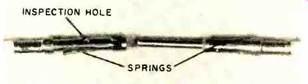
Fig. 1. A crimped pin and its mating socket, with wires already inserted.
One connector may hold hundreds of these.
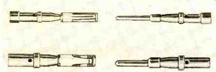
Fig. 2. Two of the many available pin –and-socket pairings.
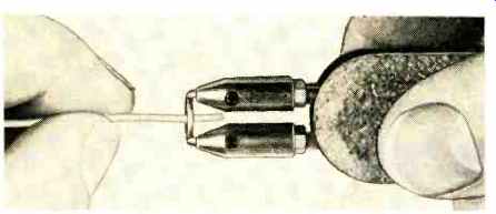
Fig. 3. Using a thermal wire stripper. Heat melts insulation.
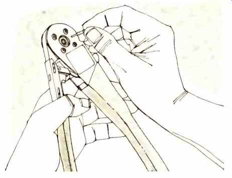
Fig. 4. A single contact being inserted into crimping tool.
Interconnecting devices are available in a wide range of types, sizes, shapes, and cost. One may encounter a single-contact plug and jack; on the other hand, a connector in modern digital equipment may have several hundred contacts. In critical applications, these devices must be temperature-stable, moisture-proof, and otherwise have high reliability.
Until a few years ago, the contacts of most connectors were permanently fixed in the insulator body, with each wire soldered to its respective contact. If wiring up a large number of closely spaced pins without spilling solder or producing cold solder joints was a prodigious feat, inspecting the connector to make certain that all joints were good was nearly impossible. In a chain of otherwise highly reliable equipment, connectors often proved the weak links.
A well established technique borrowed from the electrical-appliance field has now superseded the soldered connector, where reliability is a factor. New connectors use removable rather than fixed contacts and each of the latter is crimped to its wire rather than soldered. The great advantage of removability is that any contact can be taken out and replaced without disturbing the rest of the assembly. As to the solder-less technique, there appear, at first, to be certain disadvantages. But they are easily overcome.
In crimping, a stripped wire is simply inserted into a metal sleeve or other opening in the contact and the surrounding sleeve is squeezed tightly against the wire. If the sleeve is too large (or the wire not large enough) , the individual strands will have room to shake loose. The wire can also pull loose if the squeeze is not tight enough. If the squeeze is too tight, on the other hand, strands in the wire may be broken, resulting in weakness.
The sleeve metal can also be a factor. If it is too springy, the crimp will eventually lose its tightness. If it is too brittle, the crimping operation will cause cracking and the weakened connection will eventually break off. Thus, although crimping is faster and simpler than soldering, it has its own problems. Counterbalancing these, however, is this fact: when the proper tools and techniques are employed, crimped joints can be perfect. Control of this factor is easier than with soldering.
Before going into methods, however, let's consider connectors and their contacts a little further.
Connector Variety
Like earlier types, modern connectors vary in size and shape according to application. The range in the number of pins (or matching plugs ) , as has been noted, may be from a couple to a few hundred. Shape may be round or rectangular. There are always two mating elements and, in most cases, one of them is mounted firmly to a larger object. For example, there may be a chassis connector that mates with a cable or a printed-wiring board connector that mates with contacts directly on the board. In some instances, both connecting elements are mounted on separate, solid entities. Consider computers, laboratory oscilloscopes or generators, and other devices with removable sub-assemblies. These generally use plug-in drawers or subchassis.
Some means of keying or guiding is invariably used to make certain that pins and sockets mate correctly. A few years ago, many connectors depended only on pin distribution and arrangement for this. All newer types use some other means, to prevent damaging attempts at forcing connectors together in the wrong way. Round connectors generally use a keyway in the shell, as do octal-base tubes. Rectangular types use either non-symmetrical shell shapes or else a set of sturdy keying posts, larger than the contact pins, to prevent wrong mating.
There is also more sophistication and more reliability in the pins and mating sockets that form the contacts, some of which are shown in Figs. 1 and 2. On the glamorous side, they generally use gold over nickel plating. They also include spring elements to insure good contact and firm seating in the connector's insulating material, just in case a pin or socket does become defective, it can be removed and replaced without disturbing the rest of the assembly. As a rule, however, a special tool is required, just as crimping calls for its special tools.
In some cases, the implements required for one type of connector are slightly different from those used with another.
Even so, anyone familiar with the tools and techniques associated with one connector type or a particular manufacturer will also be able to handle others. This ability is the key to reliability and repeatability.
Crimping
The secret of successful crimping lies in choosing the right wire size for a particular connector and in preparing that wire properly. The length of wire that is to be bared, which is specified, must be just right so that it will fit into the crimping well, while remaining insulation must fit cleanly into the sleeve provided for it. Most contacts incorporate a small hole in the crimping well for inspection.
The stripped wire should not be nicked, nor should any of its strands be severed. This simply means that a good wire stripper must be used. There are many satisfactory types popular with technicians on which the only precaution is that the correct die size be used for the wire involved. However, unless Teflon insulation is used, a thermal stripper is preferred. A simple one, which melts away insulation without damage to the conductor, is shown being used in Fig. 3.
As for crimping tools, only those designed for the particular type of contact should be used, and use of the correct die size is essential. The tools are available with assorted, changeable dies to fit the various sizes of contacts in the line and appropriate wires. Fig. 4 shows a pin being inserted in a crimper.
In Fig. 5, the stripped wire has been inserted into the pin and the handle is being squeezed to make the crimp. In most cases, there is a ratchet mechanism that prevents release if the tool has not been squeezed all the way, to insure a proper crimp.
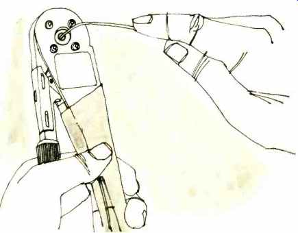
Fig. 5. A wire is inserted into contact, handle is squeezed.

Fig. 6. Enlarged cross-section of wire strands in oval crimp.
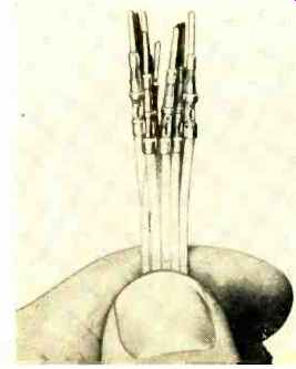
Fig. 7. A set of crimped pins ready for connector insertion.
Depending on manufacturer and connector type, the crimp itself may be in the form of an oval, star, or other shape. An enlarged cross section of an oval crimp (Fig. 6) shows how tightly the individual wire strands are squeezed and how they bite into the inside of the crimp well. In a properly made connection, the mechanical strength of the joint is much greater than that of an equivalent one made with solder. A portion of the insulation is supported by the sleeve extending from the crimp well, so that the wire can flex only over the insulated portion while the lower part is held rigid. Fig. 7 shows a bundle of wires crimped onto individual pins, before they are inserted into the connector.
Insertion and Extraction
Each pin (or socket) is first slipped into the correct hole of its connector (Fig. 8) by hand, then pushed all the way clown with the appropriate insertion tool. Note that insertion is made through the back end of the connector; that is, the pin will go through the body to protrude at the opposite side.
The insertion tool, which is matched to the contact, is a hollow, half-open shaft, with space in the hollow for the wire, as shown in Fig. 9. It is pressed down until its own shoulder rests on the insulating material of the connector, as shown in Fig. 10. At this point, the pin or socket is held in the connector body by spring action, which is provided by springs either on the body of the pin itself (as in Fig. 1) or in the connector. The insertion tool can then be withdrawn easily.
To remove a pin or a socket, another type of implement is used to overcome the tension of the retaining spring. An extraction tool is always applied to the mating end of the connector ( Fig. 11) rather than from the back, as is the insertion instrument. The extraction tool fits either around the pin or into the socket. Thus the types used for male and female connectors will not he the same.
For the type of contact shown in Fig 1, the extraction tool is designed to squeeze in the retaining springs on the contact itself as it pushes the contact out through the back of the connector. Where the retaining springs are inside the connector body, the tool is designed to press them away from the contact body. In either case, the purpose is to permit the removal of individual pins or sockets without damage. A contact can be inserted and extracted many times in safety. This is very helpful when errors occur in wiring a connector. If the wire itself should be damaged, however, a completely new pin or socket must be crimped on. The crimp itself cannot be repaired, as the metal is weakened.
Rules and Precautions
Just as certain "ground rules" must be observed when soldering connections, there are principles to follow with crimped connectors. The stripped wire must not be damaged in any way. It must be cut to the right length, so that the bare portion just fills the crimping wall. Insulation must fit into the sleeve provided for it. Both wire and insulation must be of the size specified for the connector. While it is obviously poor practice to use undersized wire, it is equally wrong to try to make oversized wire fit by cutting away strands.
Always use the correct insertion and extraction tools. The use of awls, screwdrivers, needle-nose pliers, scribers, and the like can damage the connector body or weaken the wire where it enters the sleeve. Often these devices will appear to be effective and give the impression that a repair has been completed successfully, but long-term reliability of the entire connector is almost certainly impaired.
If an emergency repair must be made when the right tools are not available, it is wiser to bridge wires across the connector. These leads will clearly mark the measure as temporary until the right implements are available.
In practice, such emergencies can be avoided easily. Most manufacturers of equipment using crimped connectors furnish a complete set of the appropriate instruments as part of the maintenance kit of spare supplies. Where this is not done, whoever is responsible for maintaining the equipment should insist that the proper tools be ordered before such tools are needed.
NEW CONNECTORS AND TECHNIQUES
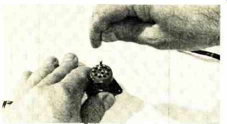
Fig. 8. Contact is first inserted by hand, but only part way.
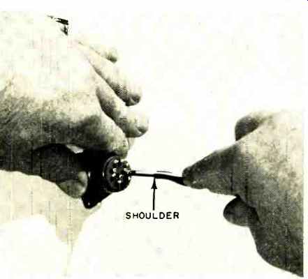
Fig. 9. A special tool, shown ready here, will do the rest.
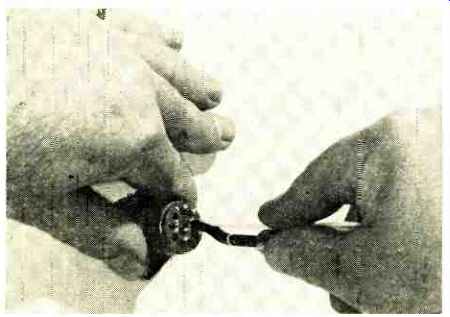
Fig. 10. Press the insertion tool and the job is completed.
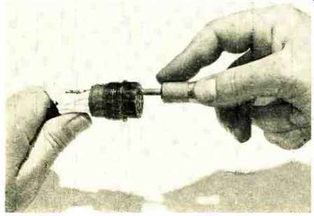
Fig. 11. Extracting a contact also calls for a special tool.