(source: Electronics World, Jul. 1963)
By DUANE H. COOPER / Dept. of Electrical Engineering, University of Illinois
Growing dissatisfaction with stereo discs may be due to greater tracing distortion and increased vertical tracking error. Means for reducing these effects are suggested, leading to improved stereo.
EVERYBODY knows that stereo sound is a more opulent sound than is monophonic sound. The improvement over mono is so remarkable that low-fidelity (called "high-fidelity," of course) stereo phonographs sell themselves on the crudest listening tests, in preference to mono, practically every time. As is to be expected, prolonged listening at hone brings an inevitable disappointment. Can it be that the same disaffection is creeping, however slowly, upon the owners of top-quality component systems? There are reasons to think so.
The fact is that serious listeners are becoming increasingly aware of a stridency in the sound of their stereo records, as more and more letters to the editors of hi-fi magazines testify. The charge is made that the recorded sound has been “doctored" to produce a more brilliant effect on cheap phonos. Some hope, with a certain measure of desperation, that 12-inch, 45-rpm records will restore to stereo the clean sound of the mono LP, while others turn to pressings mastered from 35-mm. magnetic film.
In selecting recordings, broadcast engineers and programmers are finding that FM stereo imposes severe requirements on recorded material. Many listeners will receive only the compatible mono signal. Thus it happens that stereo recordings must meet the test of sounding good when heard in the mono mode, as good as mono recordings sound.
With a good system, it is easy to discover that the stereo recordings that will meet such a test are rather few. One simply switches the stereo system to the mono mode and resolves to leave it that way for a week or so in order to condition the critical faculties to the values of mono sound.
During this period, both high-quality mono and stereo discs are to be played, using a variety of labels. Lush orchestral passages, recorded at high level and great separation, are more likely to offend, but small string ensembles can grate as well. Of course, it is scandalous to listen to stereo records in the mono mode when the full stereo system is available.
The greater scandal is that, shorn of the sumptuous stereo effect, too few stereo discs will stand comparison with mono recordings.
It is not necessary to conclude that distortion, currently running to dozens of percentage points, is sounding the death knell of the stereo disc, or that tape must displace it. Whit is necessary is that the sources of distortion be more widely understood, so that preventive measures can be undertaken by the recording industry. The two principal sources of distortion are tracing error and vertical tracking angle error.
Tracing Distortion
Tracing distortion is the more difficult to correct, although audio-design authority Professor F. V. Hunt of Harvard has recently proposed a method of tracing-error compensation. Line a of Fig. 1 illustrates an extreme case of tracing error. It depicts a sine wave recorded with such a wavelength and amplitude that the spherical stylus tip just fits in the depressed portion of the groove. No sooner does the tip fit into the depression, than it must pop out again, so that the center of the spherical tip, e, traces a curve with sharp turning points. The total harmonic content of such a wave is about 23 percent.
The acceleration at the turning points is several thousands of C's, in familiar space-age terminology. With milligram stylus masses, the record material yields ( elastically, it is hoped) under the resulting force so that the corners are actually slightly rounded. Otherwise, the accelerations would be infinite.
While the case illustrated is extreme, it can occur if a 2-kc. tone, recorded at 20 cm. /sec. (r.m.s.), is played with a 0.7-mil stylus. A definite sharpening of the troughs is noticeable in one of the author's frequency-test records for an 8-kc. tone recorded at 5 cm. /sec. When the maximum curvature is one-fifth that needed to make a close fit to the stylus, the harmonic distortion is five percent. The same distort on is less severe in mono recordings since the other groove wall carries an exactly complementary signal. The resulting push-pull geometry prevents an asymmetric tracing, so that the dominant second harmonic content cancels out.
Professor Hunt's scheme for tracing compensation calls for an intermediate cutting to be traced by the intended stylus, as in a of Fig. 1. The resulting signal is to be used, with reversed polarity, to make a second cutting, as shown at b, to serve as the master. Here the groove wall, with its projecting sharpened corners, may be traced as a distortion-free sine wave, as would be the case in the final pressing. Also, the dynamic stylus forces are substantially reduced, with the result that the record material suffers smaller deformations, making for an extended life.
Other means of reducing tracing distortion require (1) a reduced recording level, resulting in sacrifices in dynamic range, or (2) a more sharply pointed stylus, requiring lighter stylus forces, if record life is not to be reduced.
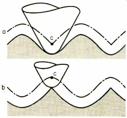
Fig. 1. Generation and remedy for tracing distortion. Line "a" shows
a groove wall being traced by a stylus whose spherical tip just fits in the
hollows of the recorded sinusoid. The center of the stylus, "c," traces
a curve with sharp turning points. At "b" is shown the effect of
tracing compensation proposed by Professor Hunt. The tracing from "a" is
used to drive a cutter, but with reversed polarity, to form the groove wall
at "b." The resultant is then traced without distortion.
Vertical Tracking Error
The cure for vertical tracking angle error, however, requires only a meeting of minds within the recording industry and among cartridge manufacturers. Distortion arises on this account because the surfaces in which the reproducing stylus and cutter stylus move are not at the same angle from the groove. The disagreement has primarily to do with the vertical. For a long time the Westrex cutter, with a "vertical" motion 23 degrees from the true vertical, has established a standard for the industry. However, the RIAA voluntary standard is 15 degrees. The corresponding European standard (IEC) has not yet been set, but 15 degrees has been proposed. Meanwhile, pressings are being made with vertical cutting angles ranging from true vertical (0 degrees), and 8 degrees, to the 23-degree Westrex angle, by the various companies.
The cartridge makers are in a similar state of disagreement. One famous cartridge has a vertical tracking angle of 40 degrees, another, equally famous, uses 30 degrees, while yet a third uses 15 degrees.
It is easy to see how the distortion comes about. One simply gets out a table of sines and plots a sine wave, as was done in a, Fig. 2. A skew projection of these plotting points is made onto a new axis, line b of Fig. 2. The original plotting points are no longer equally spaced along the new axis.
They are the basis for the erection of the distorted curve at c, using the same values from the sine table, as before.
The harmonic content of the distorted wave is about 35 percent, for this tracking angle error of about 27 degrees and an r.m.s. velocity about equal to the groove speed.
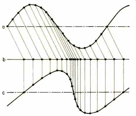
Fig. 2. Construction showing tracking distortion. The plotting points of the
sinusoid at "a" are projected by skew lines to "b." These
points, whose spacing is now modulated, are the basis for the construction
of the distorted wave shown at "c." The angle of the skew lines differs
from the vertical by the amount of tracking angle error, shown as about 27
degrees.
Harmonic distortion is not the whole story. There is an intermodulation and a cross-modulation of an FM character.
The plotting points may be imagined to mark the alternating crests and troughs of a weak high-frequency wave superposed on the one plotted. The varying spacing in these points on the axis of line b displays the frequency modulation. In the case plotted, the peak frequency shift is 70 percent of its nominal value (50 percent, r.m.s.). The r.m.s. phase-modulation index is 4.5 (450 percent!) . It does not matter whether the plotting points mark the peaks and troughs of the high-frequency wave as recorded in the same channel ( intermodulation), or in the other channel (cross modulation) in the same groove; the modulation is the same, as long as the large-amplitude lower frequency wave is traced askew.
The ear is not insensitive to such modulation. Psycho-acoustic experiments have shown that the ear can hear as little as 0.15 percent frequency modulation and, under certain circumstances, as little as 0.015 percent. It sounds like ordinary amplitude intermodulation, if the modulating frequency is in the ordinary audio range.
The case plotted is extreme, but much less severe cases can still result in dozens of percentage points of distortion, a distortion plainly evident to the ear. The mono case is not plagued with this amount of distortion. Tonearm designers have long made it a practice to keep lateral tracking errors to only a degree or so. Their efforts are of little help for stereo, however, in the face of the present varying practices for the vertical angle. Also, because of cross modulation, switching to the mono mode is of no help in reducing the distortion, as long as there is a substantial vertical signal tracked with an incorrect angle.
The day will come, as it must, when the distortion built into stereo records will be as small as in mono recordings, or even as that in our fine amplifiers, speakers, and matching cartridges. On that day, distortion percentages of one or two points will mean something. Until that day comes, we can only say, haven't heard anything yet!"