(source: Electronics World, Aug. 1963)
Triplett Model 630-NS Volt-Ohm-Microammeter
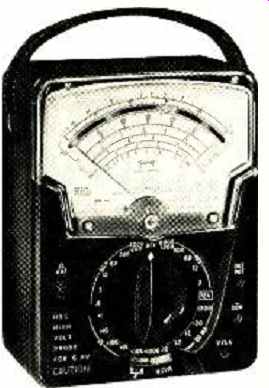
SOME interesting advances in both meter and v.o.m. design are featured in the new Triplett Model 630-NS volt-ohm-microammeter. It incorporates a suspension-type meter movement and features a wide selection of voltage and current ranges. The high sensitivity of the 5-microampere meter movement (200,000 ohms per volt) allows its use in many measurements previously restricted to v.t.v.m.'s only.
The instrument's low-voltage ranges and high input impedance make it especially useful in transistor servicing.
The low meter current allows voltage measurements with negligible loading on the circuit being measured. Even base-to-emitter bias voltages may be measured directly in most cases with minimum effect on the circuit. In most cases the Model 630-NS can effectively perform all the functions of a v.o.m. and a v.t.v.m. with its inherent advantages of greater accuracy, no warm-up, and no external power requirements. The input impedance on the 30-volt d.c. range is 6 megohms, allowing readings of 3 volts and lower at v.t.v.m. impedances. This will allow most a.v.c. and grid-bias voltages to be measured accurately.
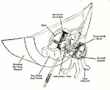
The construction of the suspension meter movement is shown in the drawing. The moving coil of the d'Arsonval-type movement is "suspended" by two ligaments, or bands, of a special platinum alloy. These ligaments are approximately one tenth the thickness of a human hair (they measure .003 by .0003 inch) and yet have a strength five times greater than that of ordinary steel. They serve three functions in the meter: to support the moving coil in the magnet, to conduct the current to the coil, and to provide the torque or spring force to return the pointer to zero. Since no pivots, bearings, or hairsprings are required, the meter is extremely rugged; it has no friction and has greater sensitivity and repeatability than previously possible with pivot-type meters. Only 0.5 microwatt is required for full-scale deflection of the basic meter. The meter also employs a special bar-ring magnet structure which provides self-shielding against stray magnetic fields.
The meter is compensated for changes in temperature from 32°F to 104°F by a special thermistor compensating circuit.
This is of particular value to the serviceman since it allows accurate measurements even when the instrument has been left in a cold service truck. Selected silicon diodes are used in the meter circuit to provide protection against accidental overloads which would normally bend the meter pointer.
Ranges on the Model 630-NS are selected by a single 24-position selector switch in conjunction with a "divide-by-two" (V-A) /2, switch. This switch effectively doubles the ranges available and results in greater accuracy of measurement since all voltage readings may he taken in the upper 60% of the scale.
D.C. volts may be measured in 13 ranges from 150 mv full scale to 1200 volts full scale. Voltages on the (V-A) /2 ranges are at 200,000 ohms per volt, others are at 100,000 ohms per volt, except 0-150 millivolts, which is at 60 microamperes. A.C. volts are measured in 10 ranges from 1.5 v. full scale to 1200 v. full scale. Sensitivity is 20,000 ohms per volts in the (V-A) /2 positions and 10,000 ohms per volt on other ranges.
D.C. current may be measured in 13 continuous ranges from 5 ua full scale to 12 amps full scale. The low voltage drop on the current ranges (150 millivolts in the (V-A) /2 range, 300 millivolts on others) is particularly valuable for measurements in transistor circuits where a higher voltage drop would affect circuit operation. The 5-microampere range allows accurate leakage measurements on all types of semiconductors including silicon transistors.
Ohms are measured from 1000 ohms full scale to 100 megohms in six ranges. The maximum open-circuit voltage on any range of the ohmmeter is 3 volts or less.
This allows ohmmeter tests on most transistors at safe voltage levels. The ohmmeter circuit is protected against accidental damage by a fuse in the input circuit.
The accuracy on all d.c. ranges is 1.5 % of full scale and 3% on the a.c. voltage ranges. The a.c. ranges are frequency-compensated to the rated accuracy from 30 cps to 20 kc. and will maintain 5% accuracy to 100 kc.
All readings are taken on a 5.5" meter which is separately housed and protected by an unbreakable front. Seven scales are provided with a knife-edge pointer and a mirror for accurate measurements. The Model 630-NS is priced at $99.50.
--------- ----------
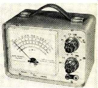
DeVry Transistorized Meter
ONE of the most useful pieces of test equipment, particularly for checking voltages in high-impedance circuits, is the v.t.v.m. Such a meter can be shunted across very large resistors and, because of the minute amount of current drawn by the instrument, will have negligible loading effect on the circuit.
Such v.t.v.m.'s are usually a.c. operated however, so they lack the convenience and portability of a completely self-contained instrument, such as a v.o.m. What is more, the v.t.v.m. is not usually able to measure current directly-and this is a real drawback when working on transistor circuits.
The new DeVry transistorized meter (TRVM-1) incorporates the best features of the v.t.v.m. and the v.o.m. in a single instrument. The unit is actually a " v.t.v.m." but with transistors taking the place of the usual vacuum tubes. The meter is completely battery-operated from four flashlight cells. It is ready to take measurements the instant the switch is turned on; there is no warm-up delay.
Four d.c. current ranges are included, from 50 µa. full scale to 50 ma full scale.
Even on the lowest current range, the meter will not be damaged by excessive current. In addition, there are four d.c. voltage ranges, from 1 v. to 1000 v. full scale, at an input resistance of about 1 meg. on the lowest range and 10 meg. on the three higher ranges. There are four a.c. ranges, from 5 v. to 1000 v., at an input impedance of up to almost 2 meg. These ranges are useful from 10 cps up to 500 kc. (± 1.5 db) . Four resistance ranges are also included, from 10,000 ohms to 10 meg. full scale. The over-all accuracy of the instrument is specified as ± 3%.
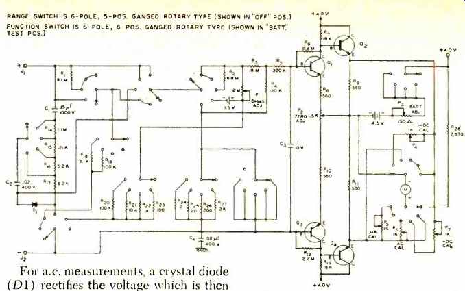
The heart of the transistorized meter is the four-transistor differential amplifier shown in the schematic diagram.
This is basically a two-stage push-pull amplifier with emitter-follower output.
The total drain on the battery is approximately 6 ma. This means hundreds of hours of operation from one set of batteries, or as much as 1000 hours with intermittent use.
All transistors are silicon n-p-n types and provide extreme reliability. Operated far below normal voltages, they should never require replacement. The output transistors, Q2 and Q4, drive the one-milliampere meter movement that is connected from one emitter to the other. The amplifier circuit is designed so that the current through the meter movement can never exceed a safe value regardless of overload at the amplifier input.
Separate calibration potentiometers are switched in series with the meter movement on + d.c. voltage, -d.c. voltage, d.c. current, and a.c. voltage positions of the function switch. A separate position of the function switch connects the meter movement as a conventional voltmeter to check battery condition. A potentiometer adjustment can then be easily made to compensate for battery aging.
For a.c. measurements, a crystal diode (D1) rectifies the voltage which is then applied to the transistor amplifier. This diode operates at the same voltage on all a.c. ranges. As a result only one a.c. scale is required. No a.c. balance of the type used in v.t.v.m.'s is necessary.
The ohmmeter circuit permits the use f external batteries to extend resistance measurements to 100 megohms and +40 V higher if this is ever required. It also eliminates any drain on the ohmmeter battery if the function switch is left in the ohmmeter position for long.
The transistorized meter is available directly from the manufacturer completely wired at $89.50, and in kit form at $64.50.
-----------------------
Keithley Model 121 Wide-Band R.M.S. Voltmeter
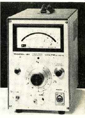
BY measuring the heating effect of an applied a.c. voltage, the new Keithley Model 121 wide-band voltmeter is capable of indicating the true r.m.s.
values of complex a.c. voltages. The instrument is able to do this over a frequency range from 15 cps to 50 mc. The wide-band response of the unit minimizes errors due to attenuation of harmonics. For example, ten harmonics of a pulse train having a 5-mc. fundamental will be passed. Accuracy is within 1 percent up to 10 mc. Twelve voltage (and db) ranges are provided, from 1 millivolt full-scale to 300 volts full-scale.
In addition to measuring complex voltages, the voltmeter can be used to measure noise in components, white noise in electronic equipment, and waveform distortion. It will also find use in the fields of vibration, sound, and optics, and for the calibration of other a.c. equipment. The meter amplifier can be employed as a low-noise scope preamp, with a usable frequency response from 10 cps to 100 mc.
Special epitaxial transistors are utilized for the wide-band amplifiers because of their high gain-bandwidth product. The basic circuit is that of a conventional feedback amplifier, and no inductive peaking is used to extend the high-frequency response. The high-gain transistors permit the use of sufficiently low value collector load resistors to minimize the effects of shunt capacitance.
Hence, the high frequencies are not rolled off. Also, 100 db of negative feedback keeps the response flat and provides gain stabilization.
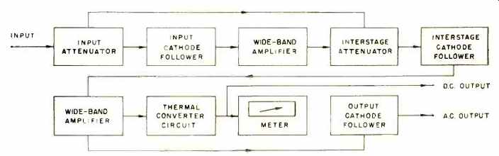
The input cathode follower is a nuvistor tube. This provides an input impedance of 1 megohm shunted by 20 pf.
The tube is used in order to withstand signal overloads. For example, it withstands overloads of 50 volts r.m.s. at signals below 100 mv and up to 400 volts r.m.s. on the 300-volt range.
The thermal converter circuit employs a thermocouple and a chopper-stabilized amplifier to insure stability and fast response. It is self-balancing with the output voltage of the thermocouple always maintained at a constant 100-mv. d.c. level. With no applied a.c. signal, the thermocouple output is maintained by applying a d.c. bias current to its heater.
When an a.c. signal is applied to the heater, its heating effect unbalances the circuit. Balance is restored by reducing the quiescent bias current. The change in bias current is proportional to the r.m.s. value of the applied a.c. signal and is read directly on the meter. A second thermocouple serves as an ambient-temperature compensator. Hence, the reading is stable and is not affected by normal changes in surrounding temperature.
The price of this special-purpose voltmeter is $870. Input impedance can be increased to 10 meg., 15 pf. by a separate cathode-follower probe for signals up to 300 mv.