(source: Electronics World, Aug. 1963)

By EDWARD K. MARRIE
Scientific Instrument Dept., DuMont Laboratories Divisions of Fairchild Camera and Instrument Corp.
One of the most useful and most versatile test instruments has made many advances in design and performance over the past decade.
SINCE its commercial origin in 1932 the cathode-ray oscilloscope has become a primary instrument for measuring electrical waveforms. It is used in a wide variety of fields and applications. Although oscilloscope manufacturers employ techniques that have brought the instrument from a simple indicator to a device that can measure electrical quantities accurately, the basic system concept has not changed. Exceptions are the new traveling-wave and sampling oscilloscopes which are special-purpose instruments.
Unlike many measuring devices, the cathode-ray oscilloscope enables rapidly varying analog information to be obtained. If the applied signals have random amplitude and time fluctuations, the oscilloscope must be employed. Scopes are multipurpose instruments combining features of both a.c. and d.c. voltmeters, ammeters, frequency and phase meters, waveform analyzers, and a good many more.
Types and Applications
Because it finds use in so many diverse measurement applications, no one oscilloscope can contain all desired characteristics. If scopes were to be classified into three general groups, these would probably be: (1) general purpose, low frequency, (2) general -purpose, high-frequency, and (3) special purpose.
Just what constitutes low and high frequency depends on the range of frequencies required by industry at the time.
In the early years of the oscilloscope, much of the electrical industry was concentrated in the area of a.c. power where scopes having bandwidths of only 10 kc. were sufficient. As the radio industry began to grow, a need developed for oscilloscopes which could be used to check out carrier and audio channels, modulators, and discriminators. To make such measurements the bandwidth of the oscilloscope was pushed to 200 kc., a wide-band instrument around 1942.
Techniques developed for military systems during World War II were quickly adapted for scope circuitry to keep up with the expanding electronics industry. Distributed amplifiers began to replace the cascaded pentode amplifiers to fulfill the 10- to 20-mc. requirements of post -war industry.
Distributed amplifiers using tubes are now being phased out of newer equipment in favor of solid-state devices. High frequency in an oscilloscope today usually means 25 mc. or above. In two or three years this will probably be changed to 50 mc. or above.
The pressure for higher frequency instruments comes mainly from users and designers of advanced military systems and computer manufacturers. Already computers have reached a point where scopes with bandwidths of over 50 mc. are preferred in design work, or with 25 -mc. passband for servicing.
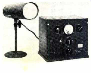
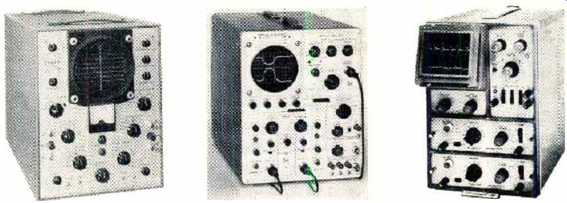
------- One of the very earliest oscilloscopes was the Type 126, manufactured
in 1932 by the Allen B. DuMont Laboratories. Having developed a practical,
long-lived cathode-ray tube, Dr.
DuMont's first use for these tubes was in instruments of this type. The power -supply circuitry was in the cabinet shown while another cabinet, not shown, housed the sweep circuits that were employed with the separately mounted CR tube.
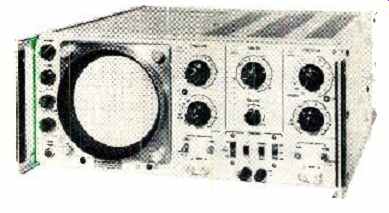
An example of a high-sensitivity, general -purpose lab scope is the Fairchild-DuMont
704. identical vertical and horizontal amplifiers are used with sensitivities
of 0.2 mv. /cm. and bandwidths from d.c. to 500 kc. The triggered sweep
is wide range from 0.1 µsec. /cm. to 1 min. /full scale. Critical circuits
use silicon transistors. The amplifiers are within ±10 relative phase shift
to 100 kc. Price of the oscilloscope is $645.
--------
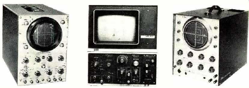
---- Designed for production and servicing of black-and-white and color-TV
receivers is the RCA WO-91A. The scope can measure color-burst signals
and can be used to troubleshoot wide -band color circuits. Either wide-band
(10 cps to 4.5 mc.) or high-sensitivity (50 mv. pp /in.) operation is
provided. Price of unit: $249.50.
Although most scopes use electrostatically deflected 5" tubes, the ITT LS -411 uses a magnetically deflected 14" CRT for display. With its plug -in amplifier and sweep modules, it can display low -frequency waveforms from d.c. to 25 kc. For use with analog computers and telemetry systems. Basic price, less plug-ins, $1965.
Another example of a general -purpose wide -band instrument designed mainly for black-and-white and color -TV servicing is the Jackson CRO-3. When switched to wide-band operation, the response is from 20 cps to 4.5 mc. When set for high sensitivity, 18 mv. r.m.s. signal produces a deflection of 1 inch. Price of unit is $234.95.
--------
Oscilloscopes having low -frequency characteristics are still required in industry. Many applications where mechanical or hydraulic systems are involved need electrical test equipment having a bandpass of only 500 kc. This class of instrument has had a fairly constant market for the past -few years but does not have the growth potential of the high-frequency instruments used in the electronics field.
New and more sophisticated sweep circuits had to be developed for the higher frequency instruments. Originally saw-tooth sweep generators used thyratrons. These were free running sweeps which could be locked to the synchronizing signal. Gas -tube sweep generators of this type had a maximum repetition rate of about 40 kc., or a minimum sweep time of about 25 microseconds. To examine a 20-mc. sine wave, a minimum of 0.1 µsec. or 100 nanoseconds was required. More complicated and versatile saw-tooth generators such as the bootstrap and Miller integrator were devised.
In most present-day equipment, the Miller integrator is used because of its linearity and fast starting. The sync signal in this "triggered-sweep" system changes the state of a multivibrator which starts the sweep. Another feature is that the method or mode of triggering may be altered. By changing the mode of operation, a triggered repetitive, free-running, single or automatic sweep may be obtained.
Single sweeps have become more important since the development of oscilloscope recording cameras where a transient will start the sweep and activate the camera shutter at the same time. Triggered sweeps of this type produce linear sweeps of 5 nanoseconds.
To make scopes easier to operate, and due to the increased accuracy of the Miller sweep system (3%), newer instruments are calibrated directly in time. At present, the Miller sweep generator is restricted to either electron-tube or hybrid circuits. However, field-effect transistors, which are now becoming commercially available, will enable completely solid-state sweep generators to be built.
With the advent of pulse and digital circuitry, a new type of display was developed to single out and expand certain portions of a pulse train. At first it was sufficient to automatically change sweep rates during the sweep to produce a "notch." This notching technique, a forerunner of the delaying sweep, worked well for instruments which had a pass band of 5 to 10 mc. As radar, pulse modulation, and computers became more refined and transportation of electrical information became faster, a new system was needed. It was important not only to know what pulse in a given train was being measured and its waveshape, but also its time relation to other waveforms in a system. To do all three jobs well, the modern delayed sweep was devised. Practically all missile projects require a number of scopes having delayed sweeps for systems check out.
Very accurate phase measurements at high frequency is another area which employs delayed -sweep scopes. In this method, a calibrated delay dial is used to measure phase.
Two types of instruments used for special high-frequency measurements are the traveling -wave and sampling oscilloscopes. The traveling-wave scope has been designed for measuring very fast, single-shot or low-repetition-rate signals.
Unlike the general-purpose scope, it does not have a vertical amplifier, but connects the signal directly to the CRT deflection plates. Second, the vertical deflection plates are divided into sections to reduce the transit time of the electron beam through the plates. These various sections are connected together with a delay line so that the signal progresses from one plate to the next in much the same manner as in a distributed amplifier. This instrument, which is usually used with a camera, provides a means of recording very fast transients. Reduction in sensitivity and scan must be tolerated in this system to achieve necessary bandwidth.
For higher bandwidths, a more versatile instrument, the sampling oscilloscope, may now be obtained. Using new solid -state components, sampling oscilloscopes will yield bandwidths over 1000 mc.
The sampling oscilloscope is closely analogous to a stroboscopic light for visual observation of rapid motion. Both techniques appear to slow down motion and depend on repetition of the phenomenon to build up the apparent image. Sampling differs from conventional display in that for each occurrence of the input signal only a single point or sample of the input is displayed. The amplitude of this point is proportional to the signal amplitude at the instant of time the sample is made. By sampling at slightly different times for each input cycle, a display showing the entire waveform is produced.
With this method, the effective bandwidth of a fairly low frequency amplifier may be extended upward and the loss of sensitivity and scan in the traveling-wave system may be overcome.
------------
------ Another example of a wide-band laboratory oscilloscope is the
Simpson 2610. This instrument was designed to fill the gap between service
-type scopes, which have fairly limited performance but at reduced cost,
and the very high-performance, high cost laboratory instruments. Response
is d.c. to 8 mc. ( ±1.5 db); sensitivity is 6 mv. r.m.s. /in. The price
of the unit: $575.
In order to view waveforms with very short rise times, a high -speed sampling technique is used in this Tektronix 661 with dual -trace sampling preamp unit. Small bits of the signal, sampled at slightly different portions of the waveform, recreate the display. The vertical passband is equivalent to d.c. to 3500 mc.; rise time is 0.1 nsec. Price of scope and plug-ins: $3500.
An oscilloscope that uses an unusual CRT to get a dual trace on the screen is the Telequipment (Avnet) D44. Although the tube uses a single cathode, control and focusing electrodes, two completely separate deflection systems operate on the electron beam which is split in two parts.
Plug-ins are available for various bandwidths, gains. Price (basic unit): $350.
--------------
-------------
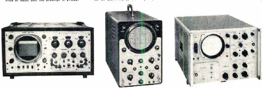
------- A special cathode -ray storage tube is the heart of the Analab
Model 1220, shown here with a dual -trace plug -in preamp. Information
can be stored for many months or it may be erased in 30 seconds. Repetitive
signals up to 100 kc. and single transients to several kc. can also be
stored. Price of basic unit (no preamp) is $1600.
An example of an inexpensive general purpose and service-type oscilloscope is the Precision ES150. The unit can also be used for low-frequency work as its response goes down to d.c. Or the high side response is -3 db at 4.5 mc. Sensitivity is 70 mv. /in. on d.c. and 25 mv. r.m.s./ in. on a.c. Price of the scope: $149.95.
Designed mainly for industrial applications, such as general production testing, computer testing, and lab use, is the Hewlett-Packard 175A. The scope has a pass band of from d.c. to 50 mc. with 7-nsec. rise time using a suitable plug-in preamp. A variety of vertical and time -base units are available. Price (basic unit): $1325.
------------
Plug-in Units
Not all improvements made to the oscilloscope have been in the electrical circuitry. More versatility has been built into the scope by the use of various plug -in units. At first only vertical preamplifiers were available. These enabled the user to select vertical characteristics for a given application. A few years ago this was extended to both vertical and horizontal channels. Sampling generators were packaged as plug -ins to permit operation of specific instruments as both standard and sampling scopes. At present scopes may be obtained which have all of the signal circuitry contained in the plug ins. Such instruments may now keep pace with the rigid specifications of present-day industrial and military applications and yet provide maximum versatility for foreseeable future requirements.
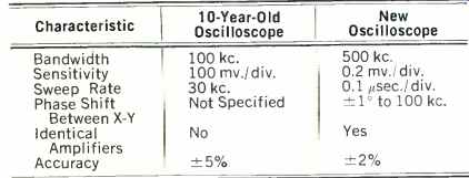
As an example of improvements that have been made in general-purpose low-frequency scopes in the past 10 years, let us compare some of the major characteristics of the DuMont Type 304 and the newer Fairchild-DuMont 704.
The following table shows the improvement in the electrical characteristics of the units. It should be noted that in the older instrument the sweep is calibrated in the number of sweeps per second whereas in the newer type instrument the horizontal axis is calibrated directly in time per division.
The latest development in oscilloscope circuitry has been the use of the transistor and other semiconductors. Although we know of no commercial oscilloscope that has been completely transistorized, semiconductors are now used in from 30 to 90 percent of the active stages in some present -day instruments currently on the market.
Advantages of Solid-State Oscilloscope
Obvious advantages of solid-state design are that the instrument will weigh less, require less space, and consume a smaller amount of power. Instruments which have the same electrical characteristics as the solid-state oscilloscope weigh from 2.5 to 3 times more, and consume over twice as much power. Tube instruments exhibit two problems which are directly related to tube aging. There is a slow degradation in the tube parameters with time. This causes trouble in the calibration and balance of the instrument. Certain types of silicon transistors, on the other hand, retain their original properties for practically their entire life.
The second effect which is found in tube instruments is a tube disease known as "cathode interface." This trouble is inherent in the vacuum tube itself and has been a constant, but unavoidable, source of trouble in high -frequency scopes until the introduction of the solid-state scope. When the tube begins to age, a resistance is developed between the heater and cathode of the tube. It acts as if an RC network had been connected inside the tube. This reduces the gain at low frequencies while not affecting the higher ones. A gradual over-peaking is therefore developed in the square -wave response. Some large companies connect clocks to their oscilloscopes and replace all the tubes in the high -frequency amplifiers every 30 to 60 days. Since transistors have neither heaters nor cathodes, this problem is nonexistent.
There is also more versatility when designing with transistors, since both n -p -n and p -n -p transistors are available.
The p-n-p transistor has no tube counterpart, since the tube would have to operate with the cathode positive with respect to the plate. In direct -coupled systems, this is an easy method of keeping the power supplies at low values.
Not all types of transistors are suitable for use in oscilloscopes. To produce a stable, solid -state scope silicon transistors are usually used. The reverse current from collector to base in transistors doubles every time the temperature increases 10 °C. Since the acceptable range of operation is between 0 and 50 °C, an extremely low initial reverse current is a prime characteristic for transistors used in oscilloscopes.
When germanium transistors are used, instability with temperature usually results due to their larger reverse currents.
Transistorized construction also makes it possible to package all the signal-carrying circuitry into plug-ins rather than having it distributed between a preamplifier plug-in and the main frame. The delayed sweep generator, which contains two complete sweeps, may be operated more easily than tube types due to its compactness. Automatic features within this unit, made possible by silicon planar transistors, decrease the number of controls on the front panel. Cabling, which had to be external in the past, is now done internally and may be changed by means of front -panel switches.
------------------
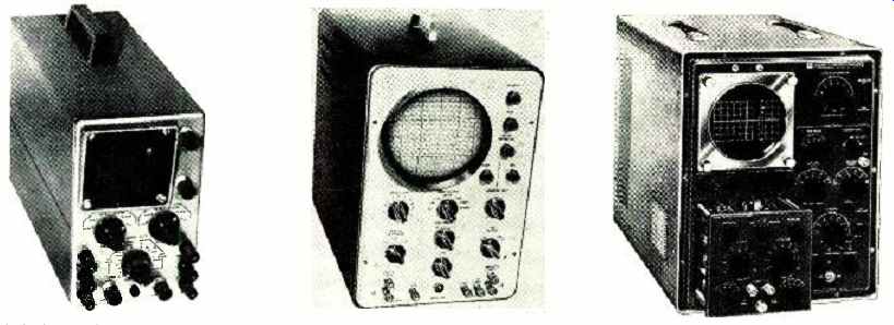
-----A 3-inch d.c. oscilloscope that is available in kit form is the
Heath IO -10. Identical vertical and horizontal channels are used with
bandwidths from d.c. to 200 kc. Sensitivities of amplifiers are 0.4 v.
(p - p) per inch. This compact scope weighs about 16 lbs. There is less
than 5° relative phase shift between channels. Price: $79.95.
Another example of a scope in kit form is the Conar Model 250. This is a 5-inch wide -band scope for general and TV service use. The vertical sensitivity of the unit is 23 mv. r.m.s. /in., and the vertical frequency response is flat from 13 cps to 2.5 mc. and down 1.5 db at 3.58 mc. Price: $89.50, or $139.50 assembled.
The most elaborate scope in kit form is the Knight 10-mc. d.c. laboratory scope shown here. This is a research -quality unit with interchangeable vertical pre amps. Built-in sweep timing markers are provided along with built-in voltage calibrator. Dual-trace preamp is available. Price without plug-in preamps is $395.
--------------------
Choosing an Oscilloscope
When choosing an oscilloscope, there are certain questions which must be answered to obtain an instrument that will avoid erroneous readings, make the required measurement,
or not become obsolescent soon. These questions are general and could be used as a yardstick for either a scope to do a specific job, or one for general use.
1. What sweep rates are necessary? Some measurements require that the instruments have fast sweep rates, while others need slow sweeps. An oscilloscope having the greatest spread between fastest and slowest sweep would seem to be the more versatile. However, two important points should be considered in determining what sweep rates are necessary.
Are the frequency response of the vertical amplifier and the maximum sweep rate compatible and what is the sequence of the sweep -rate switching? As a rule of thumb, if one cycle of the upper passband frequency can be displayed across the face of the CRT, then the sweep rate is adequate.
For example, if the passband were 500 kc., then the period for 1 cycle would be 1 /500 kc. or 2 microseconds. If this time is divided by the number of divisions in the horizontal direction, usually 10, then the fastest sweep rate required will be 0.2 microsecond per division. Applying this rule to a 25 -mc. bandwidth scope would yield the 4 nanosecond per division (4 nsec. /div.) sweep rate required. This sweep rate is not obtainable in high-frequency scopes at present and some other criteria are needed. The state of the art requires that a ratio of 5 to 1 will have to be used between the calculated sweep rate and what is available at the present time.
2. What is the accuracy of the sweep? If quantitative rather than qualitative information is required, the sweep accuracy timing should be no more than ± 5% from nominal.
Most commercial manufacturers hold the tolerance to within 3% on all ranges.
3. Is vertical delay required? Above 5 mc. the oscilloscope should have a delay built into the vertical amplifier. An exception to this is when using the instrument as an X -Y plotter where the sweep is inactive. Another application where a delay line is not necessary is when the scope is always triggered from an external source, which activates the sweep at a specified time before the signal applied to the vertical channel. Such an application is the servicing of computers where the sweep is referenced to a given point in the computer and other signals measured from this point.
4. What rise time and bandwidth are required? Normally the rise time of the scope should be 1/5 the rise time of the signal being observed. This will cause an error of about 2% when making a rise -time measurement. In general, the instrument which has the widest bandwidth is desired.
However, when working with very sensitive oscilloscopes on the order of 200 Av. per division or less, the noise level goes up as the bandwidth increases.
Excessive bandwidth in this particular case is a hindrance, since the minimum discernible signal is increased.
5. What sensitivity must the scope possess? Generally an oscilloscope is used with a high-impedance attenuator probe. Therefore, when the question of sensitivity arises, the requirement of a probe must first be determined. Ideally the sensitivity of the oscilloscope should be such that the smallest signal that will be applied will produce full screen deflection. A good rule of thumb would be the more sensitivity the better, down to 5 mv. per division. Below 5 mv. /div. excess gain will produce a widening of the trace.
6. What effect will the scope input impedance have on the item being tested? The input impedance of an oscilloscope is a paralleled RC network.
Its resistive component should always be high as possible ( say, 1 megohm or more). If a 10 to 1 probe is used, this will be increased to 10 megohms. The importance of the capacitive component will depend upon the bandwidth of the instrument. Higher frequency scopes should have lower input capacities. The use of a probe will cut the input impedance of most high-frequency scopes, above 25 mc. to 10 or 12 pf.
7. How will the scope be triggered? The scope should be able to be triggered either from an external source or from a sample of the internal signal. A trigger level and slope selector are also desirable. This provides the selection of the voltage level at which the sweep will be triggered, and the sense (positive or negative) which this triggering signal must have to start the sweep.
8. What sensitivity should the trigger circuits possess? Normally a trigger sensitivity of ',_ a major division is sufficient. Some manufacturers provide more sensitive systems. However, this extra sensitivity may cause false firing (starting) of the sweep on the random noise of the system under test.
9. Is a switched input or dual -beam scope required? Dual-trace scopes which time-share the sweep, having two vertical inputs, can normally be used in most applications where two signals are to be displayed simultaneously. This arrangement is usually smaller and less costly than the dual -beam scopes available. However, if each signal must be displayed at different sweep rates, a dual -beam scope generally is needed.
Dual-beam scopes are really two oscilloscopes built into a single case. The only exception to the above is the Fairchild-DuMont Type 425, which is a timeshared scope that has the switching done in such a manner as to provide two sweep rates which can be switched in unison with the switching that occurs in the vertical channel.
10. Will the instrument be useful 5 years from now? This is hard to evaluate since no one really knows for certain what type of test equipment will be needed in the future. However, plug -in oscilloscopes can be adapted to new requirements readily. Scopes which have plug -ins in both horizontal and vertical channels extend the useful life of the unit still further.
----------------
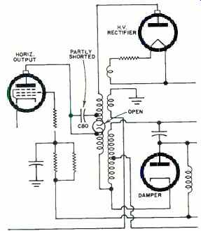
HORIZONTAL PUZZLER
By DON DUDLEY
SOFT focus and an oversized, washed out picture marked a severe case of raster blooming on a Sparton 215214 TV set. Also, one side of the picture was marred by a clearly evident horizontal sync bar, which could not be eliminated.
Replacement of the high-voltage, horizontal-output, and damper tubes made no difference. A ringing test, conventionally used to check the flyback transformer and associated components, was performed. It indicated that transformer and yoke were in good condition. Suspicious capacitors and resistors were replaced, but the symptoms remained. A continuity check of the transformer with an ohmmeter, usually less reliable than the ringing check, was then tried.
Sure enough, the winding indicated in the schematic was open. In addition, capacitor C80 showed leakage.
The partly shorted capacitor, by restoring some continuity to the open primary, permitted the transformer to function, after a fashion, and to pass the ringing check. However, circuit constants changed by the two defects altered the phase of the a.f.c. system enough to shift the horizontal sync bar into a visible portion of the raster. Replacing the flyback and the capacitor cleared up this unusual and baffling problem.