(source: Electronics World, Dec. 1963)
Featuring a built-in dot generator, this color-TV kit comes with a degaussing coil and with all critical circuits factory assembled and tested.
UP to the present time, this writer and, in fact, many manufacturers of kit equipment, felt that to design and market a color television set kit would be a foolish venture. Black-and-white TV sets in kit form have been successfully marketed, but to develop a color design seemed to have been much too complicated, as far as alignment and color adjustments were concerned, to hope that the consumer could construct one. The Heath Company, on the other hand, apparently had a different viewpoint, because they have just announced the availability of a 21-inch color TV receiver in kit form making it obvious that the apparent difficulties in alignment and testing have been solved. This new TV kit is basically an RCA design and, in itself, does not warrant much comment. There are, however, many innovations in the original design that provide foolproof alignment and color adjustment. This is the first kit, at least to the writer's knowledge, that has its own built-in test equipment. Actually there are four major points that not only simplify the alignment and color adjustment, but sufficient details are available so that anyone with a fair knowledge of electronics can service and maintain the performance of the unit for the life of the set.
As an aid to the constructor who may not have access to certain items of test equipment usually required for color set adjustment, this new kit has a built-in dot generator, provisions for shorting out the separate color guns of the tube, is supplied complete with a CRT degausser, and incorporates an instruction manual that includes a complete schematic diagram with service and maintenance information. It is, in essence, not only a service manual but, in itself, an important educational tool for those interested in knowing more about the design and maintenance of a color-TV set.
The built-in dot generator, a unique circuit in itself, is shown in Fig. 1. This circuit is used during the original convergence procedure and can be switched in at the convenience of the viewer at any time he desires to check the CRT color convergence.
The circuit consists of a synchronized oscillator operating at a multiple of the frame frequency and a ringing coil operating at a multiple of the line frequency. (If these two signals were made visible on the CRT screen, they would form a cross-hatch pattern.) The two signals are mixed in a diode that produces an output pulse whenever the two signals coincide. This, of course, would be at each intersection of the cross-hatch pattern, thus making the resulting output signal a dot pattern.
The horizontal line generator is a neon-lamp relaxation oscillator whose output frequency is controlled by R1. When the frequency is set and synchronized to some multiple of the vertical rate, then the series of horizontal lines for the cross-hatch pattern will be generated. This portion of the circuit is synchronized to the set's vertical rate by application of a pulse, via C1, from the vertical output tube.
To produce the series of vertical lines for the cross-hatch pattern, a positive-going pulse is taken from the horizontal output transformer and applied to a fairly high-"Q" coil tuned to some multiple of the line frequency. The frequency of the coil determines the number of vertical lines.
When the "Normal-Dots" switch is in the "Dots" position, the video signal from the picture detector bypassed to ground by C2 and the dot generator output signal is fed to the video amplifier. When the switch is in the " Normal" position, the output of the dot generator is bypassed to ground and the video signal from the detector is then allowed to pass to the amplifier.
During the original adjustment, or even when moving the set from one wall to another, it is necessary to demagnetize the color picture tube. Instead of depending on the builder having a degaussing coil available, Heath has taken the precaution of supplying a rather inexpensive, small-sized coil, consisting of 30 turns of # 18 wire operated directly from the 6.3-v., 13-amp. filament supply.

Fig. 1. The built-in dot generator is essentially a cross-hatch generator
with only the intersections of the vertical and horizontal line pattern showing
up as a dot pattern on the cathode-ray tube screen.
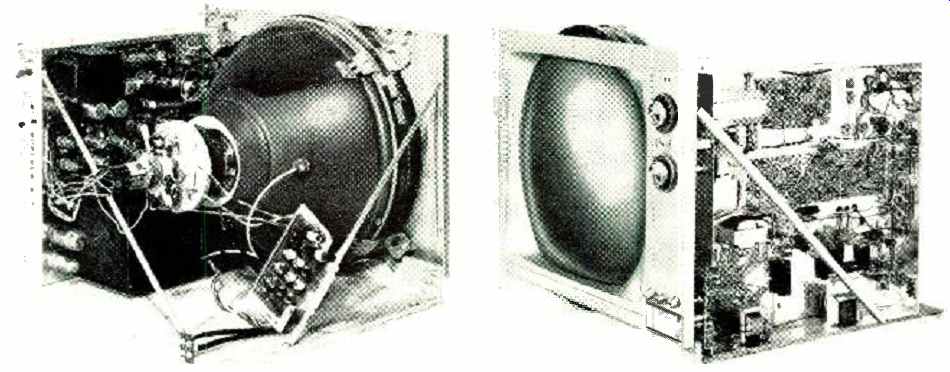
--Interior views of the color set showing the vertical chassis, with the
convergence board mounted near the CRT yoke assembly.