(source: Electronics World, Dec. 1963)
By B. V. K. FRENCH / Avco Corp., Electronics and Ordnance Division
Scaled-up version of a broadband microwave horn makes an excellent TV and FM antenna that can be mounted in confined indoor areas such as attic crawl spaces.
AMONG the vicissitudes and occupational hazards of professional existence in the electronic industry, is the necessity of compromising a desire for high-quality, noise-free TV and FM reception with the rabbit ears pick-up usually imposed by apartment-house regulations.
Having lived in apartments in five large metropolitan areas, the writer has found that apartment rules prohibit the use of an outdoor antenna, or at least one visible from outside the building; multiple ghosts are invariably present due to reflections from the framework of nearby buildings, power lines, or other metallic structures; commutator-type electrical appliances such as kitchen mixers, vacuum cleaners, and electric razors cause a high intermittent noise level in multiple-unit apartments; and conditions are often aggravated by nearby shopping centers or service stations with flashing signs, animated displays, or other electrical noise-producers.
Single unit suburban dwellings on which an outside antenna is objectionable for aesthetic or other reasons are often subject to the same restrictions as multiple unit urban apartment houses.
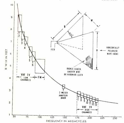
Fig. 1. Dominant mode cut-off frequency versus physical dimensions for the
broadband equilateral horn antenna described.
Under these conditions, the only possible solution lies in using the attic of the single unit dwelling or the attic crawl area of the apartment. Here, convincing the landlord or rental agency that the installation will not damage the building or constitute any greater fire or lightning hazard than is presented by the electrical wiring of the building itself, is the only major problem. The lead-in from the antenna is routed unobtrusively down the corner of a clothes closet and along the baseboard of the room to the receiver to provide a finished installation.
Elimination of ghosts and man-made noise dictate the use of antenna structures which have extremely high front–to-back ratios, high gain for horizontally polarized television and FM transmission but with reduced pick-up of vertically polarized radiation such as noise. Additional important requirements are broad frequency response and a good impedance match over the required frequency band. The last two considerations are particularly important when the desired stations are widely separated in the TV band, or when color reception is a requirement.
The choice of antenna type to fulfill these requirements depends largely upon the receiver location with respect to: number and frequency allocations of required TV broadcast transmitters; angular relationship between the incident direct signal from the transmitter and the reflected signal causing the ghost; and adequate antenna gain to produce pictures with a sufficiently high signal-to-noise ratio.
If only a single broadcast station is involved, the use of a multi-element yagi antenna array--consisting of a driven element, a reflector, and sufficient directors--will provide the required pattern for the elimination of ghosts. Adequate response at video carrier, color subcarrier, and sound frequencies dictate broader bandwidth parameters than are provided by a narrow-pattern yagi. A number of such arrays, as would be required for multiple station reception, necessitate the addition of multiple lead-in wires and cumbersome switching arrangements either at the antennas or at the receiver. Thus the yagi array provides only a partial solution to the problem.
The writer has found by experiments in urban multi-unit apartments and suburban single-unit dwellings in a number of large cities, that a scaled-up version of the familiar microwave horn admirably fulfills a majority of the requirements for a broadband antenna.
No originality is claimed for this use of the microwave horn for television reception since at least two references to such possible use have appeared in the literature.[1,3] However this application has received nowhere near the attention it deserves.
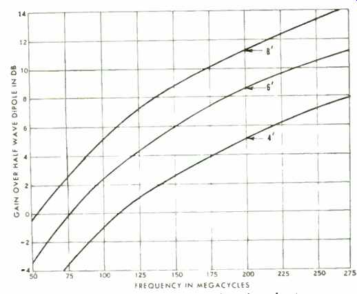
Fig. 2. Gain versus frequency for various sizes of antennas.
The early investigators of the microwave horn radiator (W. L. Barrow, F. D. Lewis, and L. J. Chu of Massachusetts Institute of Technology) in the first published articles (1939 ) [1,2] originally proposed its use as an aircraft blind landing localizer radiator, but suggested, "This (broadband) feature of the electromagnetic horn, which is perhaps not equaled in any other type of ultra-high-frequency radiator, fits it peculiarly to wideband applications like television...." The first specific application of the sectoral horn to v.h.f. television reception was proposed by D.O. Morgan (1951). He described its use as a tower mounted, fringe-area outdoor antenna for use with a rotator. In spite of its excellent performance characteristics it presents wind resistance problems and it is hardly a thing of beauty when exposed to public view. These considerations, of course, will not apply when the antenna is secreted either in the attic, or in some other convenient out-of-sight place.
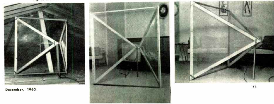
Fig. 3. The four-foot horn antenna can be disassemble d easily for installation
in any confined area such as an attic.
Theoretical Considerations
The configuration chosen for this application is a bi-sectoral, equiangular, pyramidal horn. The literature is replete with pertinent theoretical and design information .[1.2,3,4,7]. In reading these references, several items should be noted:
1. Vertically polarized transmissions (electric field lines perpendicular to the earth's surface) are employed in all radio services, except television and FBI broadcasting, therefore vertically polarized transmission is generally assumed in the literature although not specifically so stated. For this reason, illustrations should be rotated 90-degrees for application to horizontally polarized reception and the text interpreted accordingly.
2. Sectoral horn discussions are mainly concerned with "flare" (inclined at an angle) in one plane only while pyramidal horns are flared in both planes.
3. The version considered here consists of two sides only of the pyramid (top and bottom omitted) since the desired mode of reception is that for horizontally polarized waves.
In Fig. 1, dimension H determines the low frequency cutoff of the horn. When operating in the dominant mode, a half-wavelength of the electric field occurs across this dimension. The electric field distribution, across the rectangular aperture, when operating in the dominant mode is identical to that in rectangular waveguides. See any standard text.
Dimensions of a 60degree flare pyramidal horn versus cutoff for various frequencies in the television bands are also shown in Fig. 1.
As the flare angle varies, the gain of a pyramidal horn referred to a half-wave dipole goes through a broad maximum between 40 and 60 degrees. The equilateral version with a 60-degree angle is within 0.2 db of the maximum.
Such variation is negligible. The gain versus frequency characteristic of 60-degree bi-sectoral horns having apertures of 4, 6, and 8 feet are shown in Fig. 2. The reference base is a normal 72-ohm, resonant half-wave dipole.
The directional reception patterns of electromagnetic horn antennas as a function of flare angle are shown in detail in the literature.[4] While flare angles of less than 60degrees will provide narrower reception patterns, this is accompanied by a reduction in gain. The antenna polar pattern is sufficiently narrow to accomplish its purpose of ghost elimination and yet allow adequate gain over a 20° included angle. (It is of interest to note that the bow-tie antenna for u.h.f. television is a horn with a 180° angle.) For a perfect match, a lead-in impedance of 377 ohms is required. deans of attaining a satisfactory impedance match will be covered while discussing antenna construction later in this article.
Practical Construction
Many apartment houses have a slightly pitched roof construction with an attic crawl space provided for ventilation and heat insulation purposes. Access to this space is usually provided through a small trap door often located in the ceiling of a clothes closet or hallway and may be a scant three feet or less in its diagonal dimension. To meet these cramped conditions, as well as to make preliminary performance and orientation tests before final installation, a design was adopted which permitted ready disassembly. A screwdriver is all that is required for reassembly in the attic.
Fig. 3 shows the assembled antenna which consists of two equilateral triangular frames made from 1" x 2" pine furring, and covered on the facing or interior surfaces with bronze screen cloth. The frames are held together at the corners by hardware mending plates (1/6" x 1" x 2 ") fastened with wood screws. The screen cloth is tacked to the upper and lower side pieces and secured with screws and flat washers at the vertical front piece. Thus, the front parts of the frame can be removed and the entire antenna folded for passage through the attic door.
Fig. 4 illustrates some of the constructional details at the apex of the horn. The screen cloth is trimmed off at the apex corner of both sides to prevent an accidental short circuit. The nose block or brace was made by gluing together two of the 30-60-90-degree pieces of wood cut from the ends in forming the sides of the frame. ( The nose block is shaped like an equilateral triangle.) Assembly employs small angle brackets held to the sides and the nose block by 3/16 machine screws, nuts, and washers. These provide contact for feed to the receiver.
Fig. 3 (left) shows the completed antenna in position in an attic area.
Transmission Line
The 377-ohm antenna impedance will not be seriously mismatched if the usual 300-ohm twin lead is used. The loss will be about 1.3% in power or .06 db in addition to the attenuation due to the length of the line itself.
Reduction of interference due to manmade electrical noise will, in many instances, dictate the use of coaxial cable for antenna to receiver connection. This will require impedance matching at both the antenna and the receiver. An antenna-to-coax match, which is close to ideal, can be obtained by using RG62/U cable with a characteristic impedance of 93 ohms and a four-to-one matching network employing bifilar antenna matching coils. This transformer network or balun is shown in Fig. 5.
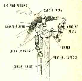
Fig. 4. Construction details of the apex.
The matching coils, also known as elevator coils, are RCA Part No. 73591 . or equivalent (Merit Coil and Transformer Corp. TV-172 or J. W. Miller Co. No. 6104) . The match from cable to receiver, 300-ohm impedance, is accomplished by the use of an identical network. In this case the mismatch 93 ohms to 300 ohms rather than 377 ohms will be found to be negligible in effect.
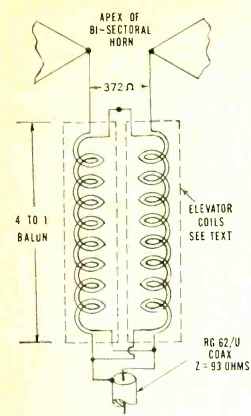
Fig. 5. The antenna–to-coaxial line matching network is a 4:1 balun transformer.
The horn illustrated is currently being used for reception of channels 5, 9, and 12. For cut-off below channel 5, the dimensions should have been 7 feet on a side. Attic dimensions limited the height to 4 feet. A trial of this size of antenna at the receiver indicated that picture quality was satisfactory on this channel and that objectionable ghosts could be eliminated on all channels. A similar compromise of dimensions for reception of low-frequency channels has also been previously discussed by D. O. Morgan. [3] While the foregoing discussion has been concerned with an application in which all three desired stations were within the 20-degree included angle of the reception pattern of a single horn, the use of two or more horns for complicated patterns can be accommodated by a simple two-pole, multiple-position switch at the receiver. In many instances the combination of a horn with a single channel yagi will suffice.
An alternative method of construction which has been suggested involves the use of overlapping strips of aluminum cooking foil taped to large sheets of wrapping paper for the triangular metallic sides.
If the antenna is to be mounted in an attic or other place where it would not be exposed to wind loading, then solid metal sheets of either aluminum or copper flashing material could be used.
The author wishes to thank E. J. H. Bussard of Aveo, E & O Division, for his helpful advice in the preparation of this article.
REFERENCES
1. Barrow, W. L. & Lewis, F. D.: The Sectoral Electromagnetic Horn," Proc. of the I.R.E., Jan. 1939
2. Barrow, W. L. & Chu, L. J.: "Theory of the Electromagnetic Horn," op. cit.
3. Morgan, D. O.: "Horn Antennas for Television," Electronics, October 1951
4. Rhodes, D. R.: An Experimental Investigation Of the Radiation Patterns of Electromagnetic Horn Antennas," Proc. of the I. R. E., September 1948
5. Risser, J. R.: "Microwave Antenna Theory & Design," Vol. 12, Radiation Laboratory Series, McGraw-Hill Book Co., Inc., 1947
6. Kraus: "Antennas," McGraw-Hill Book Co., Inc., 1950
7. Schelkunoff, S. A. & Friis, H. T.: "Antennas, Theory and Practice," John Wiley & Sons, Inc., 1952
8. Terman F. E.: "Electronic and Radio Engineering," McGraw-Hill Book Co.. Inc., 1955