(source: Electronics World, Aug. 1964)
By DAVID L. PIPPEN / Guidance and Control Labs, White Sands Missile Range
The gate turnoff controlled rectifier (GTCR) is more versatile than its SCR cousin because a negative pulse will turn it off. Some experimental circuits are shown.
DEVELOPMENT of the conventional silicon controlled rectifier (SCR) has enabled the design of many new electronic devices that were previously impractical.
The SCR is frequently employed in commercial, industrial, and military equipment and, in many applications, the SCR has replaced thyratrons, fuses, power transistors, vacuum tubes, and a host of other devices. The SCR, like the thyratron tube, does have a major limitation. This limitation is that once the device is fired by applying a positive gate voltage, the gate loses control and cannot be used to turn the SCR off.
A newly developed device, the gate turnoff controlled rectifier (GTCR), operates much as the SCR but overcomes the basic limitation of the SCR in that a negative gate voltage will turn the device off.
The circuit of Fig. 1A demonstrates the basic operation of the GTCR. S1 is a spring-return switch that will momentarily place either the positive or negative 9-volt battery into the circuit. When the 12-volt supply is applied and Si is in the center position, no current will flow through the load RL. Should S1 be momentarily placed in the "on" position, the +9-volt battery is applied to the gate of the GTCR and the device fires. Current then flows through the load, limited by the value of load resistance plus the very small resistance of the GTCR. When Si is momentarily placed in the "off" position, the minus 9 volts cuts the GTCR off and the current through the load ceases.
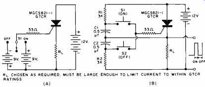
Fig. 1. (A) This circuit demonstrates the basic operation of the Motorola
GTCR. (B) Modified circuit uses the charge on two capacitors to simulate
the turn-on and turn-off batteries.
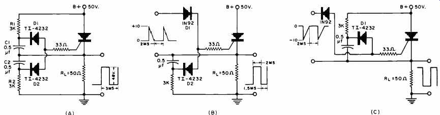
Fig. 2. Three variations of a high-power GTCR switch. (A) Free-running
type uses trigger diodes to initiate switching action. (B) Normally off
monostable version is triggered on by application of positive-going pulses.
(C) Normally on version requires a negative-going signal applied to the gate
electrode to turn the GTCR off. The GTCR is a Motorola MGCS 821-2.
Since it is not usually desired to have two batteries to turn the GTCR on and off. the circuit of Fig. 1B was devised.
Switches S1 and S2 are of the quick-return type. These switches, in conjunction with capacitors C1 and C2, perform the same function as the two 9-volt batteries of Fig. 1A. When the 12-volt supply is applied, no current flows through the load. Capacitor C1 charges through R,, and 111 to a value that is positive with respect to the GTCR cathode. When "on" switch S1 is depressed, the charge on C1 is applied across the gate–to-cathode circuit to fire the GTCR. Since the GTCR has a very low "on" resistance, very little voltage is dropped across the device and essentially all the supply voltage is applied across the load. The voltage across the load is also applied across the series combination of C2 and R2.
C2 then begins to charge to a value that is negative with respect to the GTCR cathode. Operation of S2 ( "off" switch) applies the charge of C2 across the gate-to-cathode circuit of the GTCR to turn the device off. Note that the discharge path of C2 is opposite that of C1.
Prior to introducing other circuits utilizing the GTCR, it is necessary to introduce the "trigger" or "snapback" diode since this device will be used in the remaining circuits that will be discussed. The trigger diode exhibits characteristics similar to the zener diode, but is constructed quite differently.
Four layers of doped semiconductor material are joined in either an n-p-n-p or a p-n-p-n arrangement. As the d.c. voltage across the diode is increased, the device acts as an open circuit until the "snapback" or "trigger" potential is exceeded. As the diode conducts, a negative-resistance region is realized that allows a very fast, regenerative switching action. This action can be used in GTCR circuits to great advantage.
It is realized that if a means were provided whereby "turn on" and "turn off" pulses could be applied to the gate in proper sequence, then a free-running switch with very-high power capability could be designed. The trigger diode provides a simple way of doing this.
Fig. 2A is a circuit diagram of such a free running switch. When the "B +" voltage is applied and the GTCR is off, capacitor C1 charges through R1, and R1 until the trigger potential of D1 is reached. The "snap-back" action of the trigger diode provides a fast discharge path for C1 and this discharge fires the GTCR. The "B +" voltage is then switched across R1, and the series combination of C2 and R2. Capacitor C2 charges until the trigger potential of D2 is exceeded. This allows C2 to discharge into the gate to turn the GTCR off. The cycle then repeats, providing a periodic, rectangular wave output.
The circuit given in Fig. 2A has been modified in Fig. 2B to illustrate a normally monostable switch. An externally applied positive switching pulse is applied to the gate of the GTCR through D1. The GTCR fires upon application of this pulse and conducts until the capacitor charges to the breakdown potential of trigger diode D2. The capacitor then discharges into the gate and turns the GTCR off until the next switching pulse is applied.
Fig. 2C illustrates a normally on monostable switch that requires a negative switching pulse to turn the GTCR off. In this circuit, when "B +" is applied, the capacitor charges to the breakdown potential of trigger diode Dl and the device fires. The GTCR conducts until the external switching pulse turns the GTCR off. The capacitor will begin to charge as before and when the breakdown potential of the trigger diode is reached, the GTCR again conducts and will remain in the conduction state until another off switching pulse is applied.