(source: Electronics World, Aug. 1964)
Heathkit HO-13 Spectrum Monitor

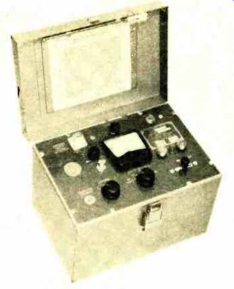
SIGNAL quality and operating habits are the topics of much discussion these days on the ham bands. The new Heathkit Model HO-13 "Hamscan" Spectrum Monitor should be able to answer many of the questions about the signals with its panoramic display of the received r.f. spectrum.
The "Hamscan" is essentially a superheterodyne receiver combined with an oscilloscope. The receiver is continuously tuned over a given frequency range and the output is visual rather than audio. Each signal received is displayed as a sharp vertical deflection of a cathode-ray tube trace ( "pip ") and the horizontal position of the "pip" is proportional to frequency. Thus, the operator can observe all signals appearing either side of the received signal. As the companion receiver is tuned, the "pip" display moves horizontally across the CRT face, with the received frequency always appearing in the center of the screen.
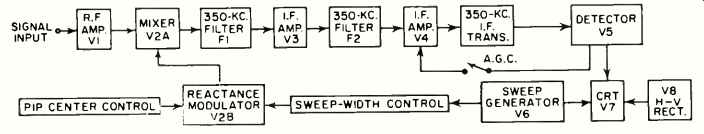
Referring to the block diagram, the signal input is obtained from the plate of the mixer stage which produces the receiver i.f. signal. The response of the companion receiver is broad at this point and enables the spectrum monitor to view as much as 50 kc. on each side of the received signal with a fairly constant response. This receiver i.f. signal is amplified by the r.f. amplifier (V1) and fed to the mixer ( V2A) where it is combined with the local oscillator signal from V2B, which is electronically tuned by the horizontal sweep signal. The i.f. frequency is fixed at 350 kc. by the ceramic filters F1 and F2 which also provide the narrow selectivity required for good "pip" resolution. The i.f. signal is amplified by 1':3, detected by V5, then fed to an amplifier which provides vertical deflection of the CRT (V7) . The detector also supplies a.g.e. voltage for controlling the gain of the i.f. amplifier, if desired. The sweep generator (V6) supplies both horizontal deflection to cathode-ray tube as well as the signal which electronically tunes the reactance modulator (V2ß). One of the outstanding features of the Model HO-13 is its inherent capability for accommodating a wide range of companion receiver i.f. frequencies. Optional components and instructions are provided for wiring the r.f. amplifier and reactance modulator circuits so that the "Ham-scan" can be assembled to operate with receiver i.f.'s of 455, 1600, 1650, 1681, 2075, 2215, 2445, 3000, 3055 or 3395 kilocycles.
The ceramic i.f. filters fix the i.f. frequency at 350 kc. and make alignment a simple matter of tuning the i.f. transformer for maximum output. In addition, the excellent selectivity obtained with the ceramic filters results in narrow "pips" which can be easily discerned even though they are within a few kilocycles of one another. Circuitry is also simplified by means of a semiconductor diode which functions as a voltage variable capacitor to tune the reactance modulator. The use of a.g.e. in the i.f.
circuit permits extremely strong signals to be accommodated without producing off-screen deflection while having little effect on weak-signal reception.
Many characteristics of received signals can be determined by careful observation of the CRT display. The monitor is just as usable with general-coverage receivers as it is with ham-band receivers since it permits monitoring any 100-kc. segment of the spectrum within the tuning range of the receiver. Operators of CB equipment will find the unit an ideal visual channel monitor which can detect the activity on channels adjacent to the one being audibly monitored.
The monitor provides approximately 1 inch of vertical deflection with a 100-microvolt input signal. A control is also provided for placing the received signal "pip" at the exact center of the screen and a horizontal gain control is provided for adjusting the horizontal size of the display. Sweep width can be varied from approximately 30 kc. to 100 kc.
The kit price of $79 will prompt many hams to add sight to sound in their shacks.
-------------------
Budelman 1744 CB Frequency Meter
The Budelman 17A4 frequency meter is a battery-operated, portable instrument which can be used for measuring up to 12 Citizens Band frequencies when equipped with only four frequency-reference crystals. The instrument was originally designed as a frequency-deviation meter to test FM transmitters.
But, since it indicates frequency error directly on a meter scale, it can be employed to check off-frequency operation of CB transmitters. When equipped with a crystal for CB channel 14, for example, it can be used to measure CB channels 13, 14, and 15. If also equipped with a crystal for channel 2, it will cover channels 1, 2, 3, and so on.
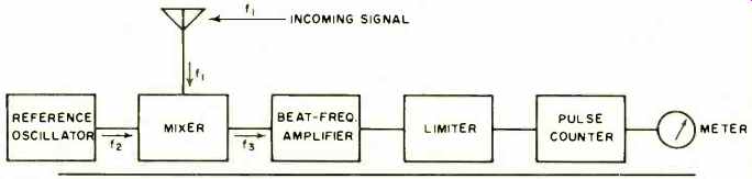
The instrument consists of a switch-selectable four-channel crystal-controlled frequency reference oscillator, harmonic generator /mixer, beat-frequency amplifier, amplitude limiter, and direct-reading counter, as shown below.
By means of a short wire antenna, the CB transmitter signal ( f1) is picked up and fed to the mixer. The reference signal (f2) is also fed to the mixer. The beat signal (f3), whose frequency is equal to their difference, is amplified, limited in amplitude, and displayed by a meter.
The reference oscillator consists of a Pierce crystal oscillator circuit and an electron-coupled amplifier, utilizing a single pentode tube. The crystal is set to the correct frequency at the factory.
The plate circuit is tuned to the second harmonic of the crystal frequency. If the crystal operates at 6781.2.5 kc., for example, the oscillator output is 13,562.5 kc. This second harmonic is fed to the crystal mixer which generates harmonics. The second harmonic generated by the diode (fourth harmonic of the crystal frequency) is at 27.125 mc. in the Citizens Band.
If the CB set being checked operates at 27.126 mc. (1 kc. off frequency) , for example, its signal will mix with the 27.125 mc. reference signal and produce a 1-kc. beat. This beat signal passes into the beat-frequency amplifier, is amplified about 55 db, and is then fed to a full-wave amplitude limiter, which changes the signal into a train of positive and negative square-wave pulses. The pulses pass through a coupling capacitor to a full-wave rectifier. Only the positive pulses pass through to the 0-150 d.c. microammeter, whose reading is in direct proportion to the frequency error.
In this case, the 15-kc. deviation scale (0-150) would be read as a value of 10, indicating a 1-kc. error.
While it has been assumed here that the CB set is operating 1 kc. too high, the instrument would give the same indication if the CB set were 1 kc. below the correct channel frequency. This can be determined by momentarily closing a switch which lowers the frequency of the reference oscillator. If the meter reading increases when the switch is closed, the CB set is operating at a frequency higher than the correct channel frequency since there is now a greater difference between the reference and measured signals. If closing the switch causes the meter reading to fall, the CB set is low in frequency.
The frequency meter has three frequency-deviation ranges: 0-1.5 kc., 0-5 kc., and 0-15 kc. The accuracy of the reference oscillator is .001% at room temperature. The price of the unit is from $310 to $385, depending on the number of crystals installed.
----------------------
General Radio Type 1396-- A Tone-Burst Generator
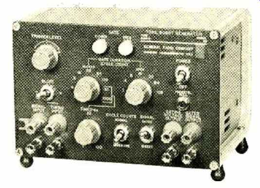
THE General Radio Type 1396-A Tone-Burst Generator is a unique instrument which, when used in conjunction with an audio oscillator, generates short, precisely controlled bursts of an a.c. signal. Such tone bursts are useful in a wide variety of time-response tests on a.c. circuits and for simulating pulsed a.c. signals commonly used in sonar and other audio-ultrasonic systems.
The tone-burst generator operates as a coherent gate, that is, the starting and ending points of each tone burst are exactly in phase with one another. (This is often required for oscilloscope display, since a steady trace is possible only with a coherent burst.) The operation of the instrument's electronic gate produces alternate periods of no output when the gate is closed and a reproduction of the input signal when the gate is open. The gate-open and gate-closed durations are set by front-panel controls. The gate-open duration may be 1, 2, 3, 4, 7, 8, 15, 16, 31, 32, 63, 64, 127, or 128 cycles.
The gate-closed duration may be ally of these or may be timed from 1 millisecond to 10 seconds.
While the above summarizes the basic principles of the tone-burst generator, a full complement of controls adds many capabilities. For instance, there are two sets of input connectors, and one signal may be used to time the bursts of a second signal. Also provided on the front panel are trigger level and slope controls, which function as on an electronic counter. The user can thus control the phase of the input signal at which the main gate opens. For use with oscilloscopes, a gating output signal of + 10 volts during gate-open and-10 volts during gate-closed is supplied.
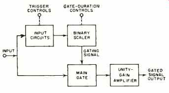
A simple block diagram is shown here. When the gate is opened, the
binary scaler advances one count per input cycle. When the number
of cycles set by the "Gate Open" control
has been counted, the gate closes and the scaler resets to zero. The
scaler then counts the number of cycles selected by the "Gate Closed" control,
after which the gate reopens, the scaler resets to zero, and the cycle
repeats. The unity-gain amplifier has a bandwidth of about 1 mc. The
maximum input frequency is 500 kc.
Nonsinusoidal signals with repetition rates up to 500 kc. can be gated provided the significant harmonics are within the amplifier's bandwidth capability.
Applications for the tone-burst generator are many. The short, precisely controlled bursts can be fed to sonar amplifiers to measure rise and fall times, pulse-envelope distortion, and frequency response. Also, many measurements (impedance, response, power) may be made on sonar transducers. The tone-burst generator may be used as a source of pulsed a.c. for bridge measurements, and as a source of transients in the measurements on loudspeakers. In fact, useful measurements may be made on virtually any audio-ultrasonic device (filters, detectors, recorders, etc. ) by means of calibrated transients from the generator.
Specifications are as follows:
Input signal, d.c.-coupled ±7.5 volts maximum, from d.c. to 500 kc., with a typical input impedance of 12 kilohms.
Timing signal, d.c.-coupled, ± 10 volts maximum, 1 volt peak-to-peak minimum, from d.c. to 500 kc., with a typical input impedance of 7 kilohms.
Gated output signal: Total distortion products are less than-60 db with reference to maximum output (15 volts peak-to-peak sine wave) at 1 and 10 kc.
During closed-gate condition, feed-through of input to output is less than-40 db with reference to maximum output.
Output impedance, 600 ohms.
The tone-burst generator is housed in an 8" x 5.25" x 6" cabinet with optional provision for rack mounting. Price is $490.
Meter Protection
By JAMES G. LEE
WHEN you want to check a d'-arsonval meter movement quickly to see if it is all right, simply wiggle the meter with the termination open and note the approximate meter deflection. Tighten short the terminals with screwdriver or wire and then wiggle the meter again.
If the meter movement is good, the deflection will he reduced drastically and should appear sluggish. The short causes a low-impedance (high current) load to appear across the meter movement as it cuts through the magnetic lines of force.
This requires a stronger turning moment than the lightweight movement can sustain. As a result, the movement becomes highly damped. If the deflection remains the same, however, it is possible that the movement is open and the meter is defective.
Using this same technique, you can protect your unused meters by simply putting a wire short across the terminals before you store them.