|
|
(source: Electronics World, Mar. 1966)
By W. A. RHEINFELDER [Applications Consultant, Dickson Electronics Corp. ]
Steps taken in converting low-level stages of power amplifiers to field-effect transistors. Comparative measurements show superior performance of FET unit.
In high-fidelity equipment, generally a much higher level of performance and quality is required than for most standard consumer electronic products. Such high standards often lead to hand-trimmed cathode resistors in professional vacuum-tube equipment, as well as the use of extensive feedback for both a.c. and d.c. stabilization. The main difficulty with tubes lies in their parameter drift with aging. This may cause a problem, for example, in the push pull output stage, where d.c. currents must be perfectly balanced in the output transformer to insure low distortion, particularly at low frequencies. Other stages, especially pentode circuits, are equally critical. Parameter changes include decreased input impedance (due to gas), parasitic generation, low-frequency sputtering, and filament leakage.
Solid-state devices should maintain their parameters over a very long period of time. Hence, solid-state amplifiers should have high reliability and be free from maintenance.
Other factors favoring solid-state designs are reduced current drain and with it, generated heat, no warm-up, smaller size, and reduced weight. Most of these advantages are of lesser importance in line-operated equipment, possibly with the exception of easier elimination of hum in solid-state equipment due to the lack of filaments.
The first approaches to solid-state hi-fi circuits were of necessity based upon standard bipolar transistors since FET's had not become available as yet. The use of standard transistors led to numerous difficulties which were overcome, however, more or less ingeniously by circuit designers.
The low input impedance of transistor circuits is, for example, readily compensated for by negative series feedback.
The noise level of transistors generally is lower than that of tubes due to the lower temperature of transistors. Distortion in normal transistors is a more difficult problem due to the fact that a forward-biased diode (base to emitter) is inherently non-linear, particularly in low-impedance circuits. This problem has been reduced by careful optimization of bias, special high- and low-level biasing circuits, temperature compensation with thermistors, and large d.c. feedback.
Many of the transistor circuits designed for extreme quality of performance appear to use brute-force methods rather than elegant engineering solutions. In other cases, quality has been sacrificed, particularly in the area of low-level cross over distortion, in order to arrive at an all-solid-state design with a reasonably small number of stages.
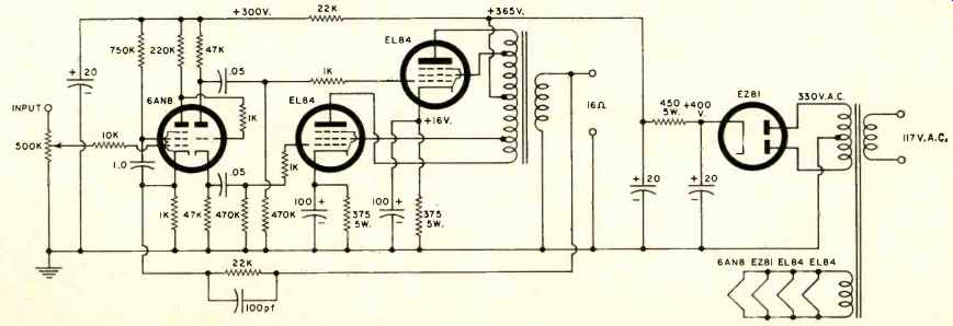
Fig. 1. A typical circuit diagram of a ten- to fifteen-watt vacuum-tube high-fidelity
power amplifier.
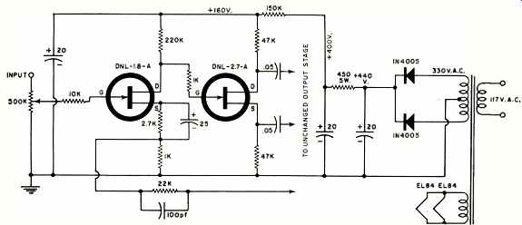
Fig. 2. Circuit of Fig. 1 modified for FET's and silicon diodes.
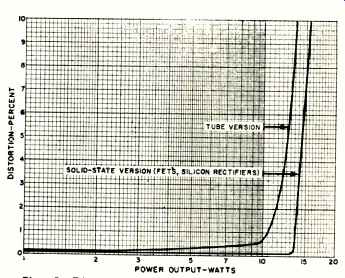
Fig. 3. Distortion and overload characteristics of both the original and converted
amplifiers.

Table 1. Comparison between vacuum-tube and FET versions.
While excellent performance is possible with present-day solid-state designs, the simplicity and quality at a given price of an ultra-linear Williamson-type power amplifier still remains to be matched with standard transistor units.
Recent improvements in field-effect transistors (FET's) have, however, opened a whole new field of applications. For the first time devices are now becoming available which are superior to conventional transistors and vacuum tubes as far as distortion, output capability, gain, noise, and current drain are concerned. Power FET's will become available shortly, and this will lead to a superior type of hi-fi equipment.
Illustrated in Fig. 1 is a typical circuit of a high-quality power amplifier. The question might be asked, "Why convert to solid state at all, as long as power FET's are not available as yet?" The answer is that in the circuit shown, serious problems of parameter drift exist. In the author's unit, which uses a similar circuit to the one shown in Fig. 1, over a period of time distortion becomes excessive, that is, audible at normal listening levels. Measurements indicated at one time a distortion level as high as 5% at 5 watts, while normally the amplifier would handle better than 10 watts at 0.6% distortion with the over-all feedback loop connected.
Tracing this condition led to the input stage. Drift in screen-grid parameters caused actual overload of the first stage. In any case, distortion could be brought down all the way by readjusting the screen-grid resistor. Optimum values ranged all the way from 150,000 ohms to 2 megohms, de pending on tube and age. Tests made with fresh tubes showed great variations also. Other triode-pentodes had higher distortion even under optimum conditions.
When FET's for large-signal voltage amplifiers became available recently, a direct conversion was attempted, with the exception of the output stage which is to be converted at some future date. Fig. 2 shows the modified circuit.
The modification is as follows:
1. Drop the supply voltage for the voltage-amplifier/ phase-splitter combination to +160 volts from the former 300 volts. This is accomplished by changing the 22,000-ohm dropping resistor to 150,000 ohms.
2. Add the resistor-capacitor combination shown in the source circuit of the first FET. Due to their lower current drain, FET's require larger self-bias resistors for proper gate bias than vacuum tubes. The values as given are correct for the transistor shown.
3. As an optional change, replace the EZ81 rectifier with low-cost silicon diodes.
All changes are easily made, and the FET's and silicon diodes are wired directly to the pins of the tube sockets.
Improvement in Performance
The improvement in performance of the FET circuit is shown in Table 1 and Fig. 3. Also, there was no change in performance with different FET's of the same type. Temperature stability of the circuit is excellent. FET's tested in a similar circuit performed without change in distortion or gain from temperatures of -50°C to +150°C, a consider ably larger range than would be encountered in practice.
The cost of FET's is at the present time quite a bit higher than that of vacuum tubes, but this is offset by the cost of tube replacement and maintenance. For example, the author in three years went through six 6AN8's and two EZ81's plus the time spent in readjusting circuit values. In a new design, a further cost reduction is possible due to a less expensive power transformer (a saving of approximately 10 watts in filament power), a smaller, more efficient chassis, and lower assembly costs.
In going over the improvements in detail, the increased power output shown in Fig. 3 is mainly due to the better rectifiers resulting in an increased supply voltage. Dissipation of the output stage had to be checked for this condition. The measured plate and screen dissipations are well within ratings. Also, the filament voltage was rechecked to make sure that it was not excessive for the EL84's. The de creased distortion below the overload point is due to the FET's. The FET circuit delivered nearly twice the voltage into the output stage than the tube circuit. While a fresh optimized tube produced 26 volts, this performance was achieved for only about one month of operation. Also, the tube needs a supply voltage of 300 volts, while the far more efficient FET produces more than 20 volts with only 160 volts.
If a higher output were needed, this could be achieved with a larger supply voltage (and special higher breakdown FET's). However, there is little need for a higher output voltage from the phase splitter even in high-power amplifiers.
For example, a pair of EL34's delivers 100 watts of audio power in class-B push-pull (with a plate supply voltage of 800 volts) for a drive signal of only 23.4 volts. This level is available directly from the FET circuit of Fig. 2. Typical commercial circuits have also been using a 6AN8 tube for this high-power application.
This change to FET's can be fully recommended and results in a superior power amplifier. Incidentally, in Fig. 1, the output stage uses individual cathode resistors. This leads to a much better balance during the life of the output tubes and is preferable to the common resistor often found.
The conversion of existing preamplifiers is more complicated, and often it is more advantageous to construct a completely new circuit. The use of FET's in such an application results in less noise and distortion together with a higher overload level. A typical high-quality circuit of this type will be described in a forthcoming issue.
Editor's Note: The FET's described in this article range in price from $3 to $10 depending on quantity and type. They arc' available from stock from Dickson Electronics Corp., 310 South Wells Fargo Avenue, Scottsdale, Arizona 85252, USA.