|
|
(source: Electronics World, Mar. 1966)
By WALTER H. BUCHSBAUM
Another in a series of articles covering unique circuit details of line-operated, large-screen transistor TV sets. This article covers the 27-transistor, 19-inch, 114° CRT Westinghouse model.
The Westinghouse Electric Corp.'s transistorized 19-inch, a.c.-operated TV receiver uses 27 transistors, a vacuum-tube high-voltage rectifier, and a 114° deflection-angle CRT. As illustrated in Fig. 1, the viewing screen is covered by a low-reflectivity type of black glass which, according to the manufacturer, provides glare-free reception and greatly enhanced contrast. As with most mod em portable receivers, removal of the back cover gives the technician access to practically all of the circuitry. Separate v.h.f. and u.h.f. tuners are used, and a special crossover net work is provided to permit both v.h.f. and u.h.f. operation with the same antenna. As shown in Fig. 1, most of the circuitry is contained on a single printed wiring assembly.
Among the transistor circuits of this receiver, we have selected three relatively unusual circuits which appear for the first time in this Westinghouse model and which will be discussed in detail.

Fig. 1. Exterior (left) and interior (right) of the Westinghouse 19-inch transistor
TV set. According to the manufacturer, the black glass reduces glare and improves
contrast.
Probably the most unusual is the power supply, which uses a voltage regulator similar to those found in transistorized power supplies for laboratory or experimental use. As shown in Fig. 2, a full-wave rectifier, D1, and D2, provide approximately 75 volts to the input filter capacitor C1. A portion of the B+ current goes through R1, a 47-ohm resistor, while another portion passes through R2 and Ql. This transistor controls the current and acts both as a filtering and a regulating element. Capacitor C5 is the output filter. A portion of the full-wave rectified signal is filtered by R4, C2, R5, and C3 and is applied to the base of Q2. This voltage appears as a well-filtered d.c. signal which regulates the gain of Q2, which, in turn, directly drives the base of Q1 to approximately set the 60-volt output level. In addition to pro viding the filtering, the combination of Q2 and Q1 also assures constant output voltage, regardless of a.c. line voltage, or B+ drain variation. This is accomplished by the sensing circuit of Q3. The emitter of Q3 is regulated by means of the zener diode. The base of Q3 is connected to a portion of the voltage between +60 volts and ground and is adjustable to provide the correct regulated voltage of + 60 volts.
Any change in the 60-volt output results in a corresponding change in the voltage on the base of Q3, which affects the current through Q3 and thereby varies the current at the base of Q2. As in vacuum-tube voltage-regulating schemes, Q2 controls the resistance, or current-carrying capability, of Q1 and thereby the +60 volt output voltage. Q1 is fuse-protected against an output short circuit. Since Q1 has to dissipate a fair amount of power, it is mounted on a heat-dissipation shelf.
The circuit shown in Fig. 2 provides adequate filtering and excellent regulation for the 60- and 12-volt supplies. The 60-volt supply is used for the audio output amplifier and both vertical and horizontal sweep sections. The 12-volt supply is used for practically all the other circuits as well as for biasing in many circuits using + 60 volts.
Another circuit deserving some description is the noise canceling circuit shown in Fig. 3. This circuit consists essentially of a single transistor, Q3, which acts as an inverter across the first video amplifier Q1.
The voltage at the base of QI is determined by the set ting of R3, the white level control. This control is factory-set to produce the best white screen picture. The output of the two-stage video amplifier is coupled to the CRT.
Noise canceller Q3 is normally cut off because of reverse bias between base and emitter. This bias is set by R4, the noise-adjust potentiometer. Diode D2 is also cut off due to reverse bias. Under these conditions, the noise canceller is inoperative until a negative-going pulse of sufficient amplitude to overcome the reverse bias on D2 comes along. When this occurs, Q3 conducts for the duration of the noise pulse.
The pulse spikes are then inverted, amplified, and coupled via C3 to the second video amplifier where they cancel the original noise spikes. Because D2 is reverse-biased when no noise spikes are received, it represents a high impedance and does not influence operation of the video amplifier.
The third circuit, the vertical oscillator, is also not entirely new when compared with vacuum-tube receivers, but it has not previously been shown in transistor sets. As illustrated in Fig. 4, the vertical oscillator circuit is the transistor equivalent of the vacuum-tube blocking oscillator circuit used in the earliest TV receivers. T1 is the blocking-oscillator transformer, coupling the signal from the collector to the base of Q1, similar to the vacuum-tube version operating between plate and grid. Sync pulses pass through a conventional integrator, R1, R2, C1, and C2 and are applied to the base of Q1 through C3 and the primary of Ti. DI applies the sync pulses to the collector of Q1 as well, while blocking the oscillator pulses. D2, connected across the secondary of T1, acts as damping diode to eliminate ringing. The frequency of the blocking-oscillator circuit is controlled by R9 (hold control) and R8 which determine the d.c. bias on the base of Q1, again similar to the technique used in vacuum tube blocking oscillators. D3 acts as coupling between the output of Q1 and the input of Q2 and assures that only the desired polarity pulse, without the overshoot portion, is sent to Q2, the driver stage for the output amplifier. Height control R12 determines the bias on the base of Q2 and therefore its amplification, while R11, the linearity control, in conjunction with C5, affects the waveshape of the pulse applied to the base of Q2.
In addition to the three unusual circuits just described, the receiver contains a number of other features. One of these is the use of +240 volts d.c. as collector supply for the video output amplifier. This, according to the manufacturer, is necessary to provide a sufficiently large voltage swing at the output of the video amplifier to drive the cathode of the picture tube. As a result, the video output transistor is a power type, having +12 volts on the emitter and +150 volts on the collector. It is mounted on the printed wiring board but contains its own finned heat radiator. The horizontal output transformer and high-voltage section are protected against damage from arcing by a special clamping diode which, in the event of large current surge, discharges into a 10-0. capacitor. This circuit is credited with pre venting the burnout trouble in horizontal output transistors which seems to have plagued earlier transistor TV receivers.
As in all Westinghouse TV receivers featuring "Instant- On," the filaments of the picture tube and the primary of the power transformer are connected to the a.c. power line at all times. While the entire receiver requires 75 watts during operation, a total of approximately 7 watts is dissipated when the receiver is turned off.
This Westinghouse 19-inch transistorized TV receiver is another interesting entry into the rapidly growing field of line-operated, large-screen transistor TV sets.
While the use of transistors does not necessarily mean a reduction in cost, or a serious reduction in the set's physical size, it does seem to mean a more trouble-free receiver. Westinghouse is so sure of the reliability of the transistor circuit that, in addition to the one-year guarantee on the picture tube, a two-year guarantee on the various component parts is also made.
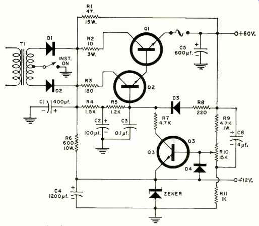
Fig. 2. The power supply for this receiver is relatively complex and features
a zener-controlled voltage regulator.

Fig. 3. The noise-canceller stage inverts the noise peaks so that they cancel
at the input of the second video amplifier.

Fig. 4. The vertical sweep starts with a conventional blocking oscillator
similar to that used in early vacuum-tube sets.