By WILLIAM SEFTON /Manager, Switch Field Applications Engineering, Centralab
Electronics Div. (Globe-Union Inc.) [The author received his B.S.E.E.
from Marquette University in Milwaukee and joined Centralab in 1956. He is
presently a member of the Electronic Industries Association's P-5.5 Rotary
Switch Committee.]
Important factors to consider in selecting the proper rotary switch are type of contacts and insulating material, whether pile-up or non-pile-up, shorting or non-shorting characteristics are required, and type of shaft.
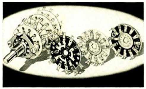
OPEN-frame, manually actuated rotary switches are electromechanical devices which are used primarily as circuit selectors in electronic and communications equipment. They are made up of an index or de-tenting mechanism, strut spacers, and screws-known collectively as the frame-and the electrical switching portion called sections. These sections have rotating insulators, or rotors; rotating current-carrying members, or contacts; stationary insulators, called stators; and stationary current-carrying members, called clips. See Fig. 1 for switch nomenclature.
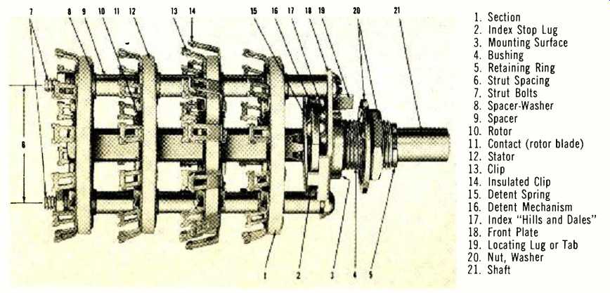
Fig. 1. A listing of the terms that are employed to describe the component
parts making up an open-frame switch.
Basic Operation & Construction
The indexing mechanism serves a twofold purpose. The first is to hold the contacts in proper relationship to the clips so that a complete electrical circuit is maintained even when subjected to vibration and shock. The second function is to act as a positioning device during rotation so that the switch tends to come to rest directly in switching position, not at an intermediate point. The more sharply an index positions itself, the better the "crispness" of the index and the better the "feel" of the switch itself.
The spacing on an open-frame switch usually has an established minimum so that the solder terminals on one section won't interfere with those on an adjacent section or with the "dead metal" parts on the index. The fact that there is virtually no limit to the maximum spacing allowed is a boon to design engineers. They can place sections in areas of the chassis to optimize electrical and mechanical requirements. Of course, when a long switch is used, there is a chance that the frame will twist. This problem can be solved by rear mounting, using screw extensions or a mounting bracket.
The switch section consists of two basic parts: a rotor and a stator. The contact or rotor blade is usually fastened to the rotor by means of "legs" formed from the contact or by rivets to hold the blade firmly in place. This portion follows the movement of the index and determines the sequence of electrical switching.
The stator or stator insulator is designed to position clips so that the contact will engage the clips in proper incremental positions. The stator must also hold the clips at a proper level so that both upper and lower clip jaws will engage the contact when the blade is rotated into position.
The thickness of the rotor and stator are selected so that the mid-point of the contact-blade material extends above the stator where the upper and lower dip jaws meet.
This causes both jaws to wipe across the blade until the index action stops the contact. This clip action is called "double-wipe" and makes the switch section self-cleaning.
Pressure of the clip jaws must be carefully balanced so that enough force is exerted to produce effective cleaning but not enough to cause excessive wear of the contact surfaces and the clip jaws.
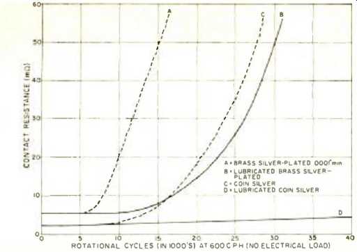
Fig. 2. Lubrication increases operational life considerably.
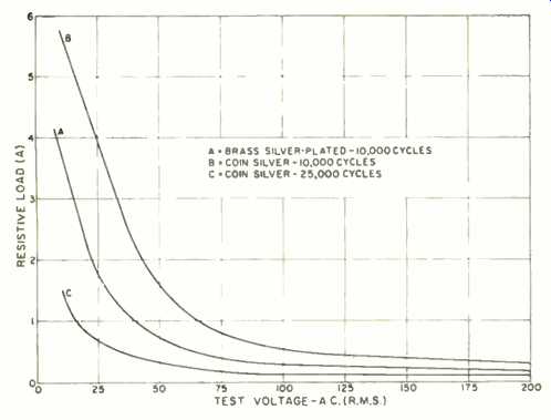
Fig. 3. Performance of various contact materials. Test sections were lubricated
and run to end of life [20 m-ohm].
above: Designed essentially as a military switch, this high-quality unit is also ideal for use in commercial equipment.
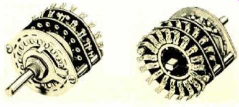
above: This open-frame rotary switch offers to the designer eighteen switching
positions, located 20 degrees apart
Lubrication and Contact Life
An "end-of-life" specification can only be given as it pertains to a specific requirement for a particular piece of equipment. This is because life parameters are too numerous to be guaranteed.
For this reason, it is necessary to pick out one limiting factor that has a specific meaning to all switch users. In rotary switches, this factor is contact resistance. It is expressed as the ohmic value of a circuit as measured through one clip, the contact, and out another clip. This path is generally measured through clips on the opposite sides of the stator, providing the longest path for current to travel.
One commonly used value for "end-of-life" contact resistance is 30 milliohms. This value, when given in conjunction with the number of shaft revolutions front stop-to-stop and return (cycles) , can then he used to express the life of a switch.
Since the standard contacts are brass, silver-plated to a minimum of 0.0001 inch, and the clips are spring brass, similarly plated, contact resistance will remain stable only as long as silver-to-silver contact exists. When a switch is rotated at the standard rate of 600 cycles per hour (c.p.h.) , the contact resistance shows an increase over the initial value (approximately 5 milliohms) at about 5000 cycles. By 10,000 cycles, contact resistance is erratic and generally exceeds 20 milliohms.
This is the switch life that may be expected when the thin film of oil used to retard silver tarnish is the only lubricant used. When a factory-approved grease is applied to the contact surface before life testing, the sections will usually withstand 15,000 cycles before the contact resistance starts to become erratic. After 25,000 cycles of rotation, contact resistance has usually exceeded 30 milliohms on one or more clips per section.
The life of a switch section can be prolonged by the use of coin silver clips and contacts. \\'hen lubricated before life testing, coin silver clips may he expected to function for 50.000 cycles or more at very stable contact resistance.
(See Fig. 3.) Brass and silver clips and contacts are tested under "no-load" conditions, so the contact resistance values obtained are valid only for light electrical loads or for circuits that du not switch under an electrical load.
When it is necessary to switch under load, switch life will vary depending on the open-circuit voltage switched and the load the clips and contacts encounter upon closure.
"Pests have been run to determine just what loads lubricated sections can switch and still maintain an end-of-life contact resistance of 30 milliohms. The graph of Fig. 3 shows a typical "load-life" curve. Note that curves A and B are capable of breaking a considerably higher ampere load for a specified voltage than the switch represented by curve C. While a load-life curve doesn't mean the physical end-of-life of the switch section, it does indicate how the load affects the physical performance of the section. The higher the load that the section must break at a particular voltage, the shorter the switch life.
Detailed information on how load requirements will affect the life of a specific switch in a particular circuit is available from the switch manufacturer and his highly trained application engineering staff.
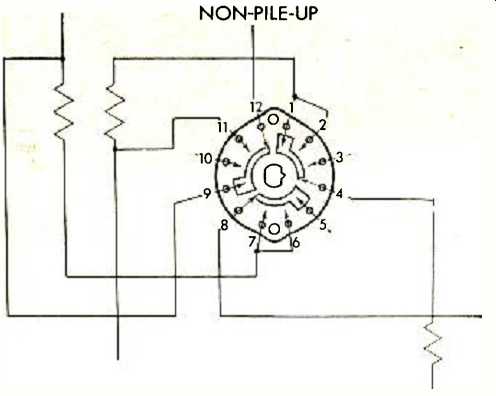
Fig. 4. With non-pile-up switching extra cross wiring is required and there
are several unused clips as shown here.
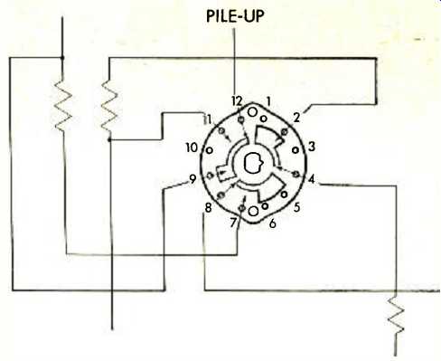
Fig. 5. Note the design of the rotor on this switch to provide pile-up switching.
Wiring to switch is now simplified.
Pile-Up and Non-Pile-Up Switching
Pile-up switching is defined as "the engagement of a contact with a clip or clips in such a manner that circuits may be maintained through more than one index position, more than one circuit may be established, or a combination of both may occur ".
Non-pile-up switching results "where the function of the contact is to engage clips sequentially and provide one circuit path when in a detent position". The action may be either shorting or non-shorting. Shorting action occurs when the engaged clip is not released until after the next clip has engaged (make-before-break). Non-shorting action therefore occurs when a clip which is engaged is released before the next clip is engaged (break-before-make). The contacts of open-frame switches are usually capable of performing both non-pile-up and pile-up functions. The advantages of pile-up switching are numerous but the principal ones include: the possibility of reducing the number of switch sections required, lower cost because fewer clips are required, and a reduction in user assembly time and materials because there is less cross wiring.
A typical section using non-pile-up switching is shown in Fig. 4. Note the cross wiring from terminals 1 to 2 and from 6 to 7. There are unused clips at terminals 3, 5, and 10. When a pile-up-type switch (Fig. 5) is used instead, the pile-up clips provide the same action that the cross-wiring provided. As a bonus, the non-standard section eliminated the unused clips, for a total savings of five clips and two cross-wiring operations.
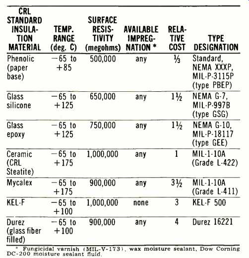
Table 1. Insulation specifications chart. Note that not all insulations
are available in every rotary switch type.
Materials Available
The standard material used in commercial and military switches is laminated phenolic NEMA grade XXXP military grade MIL-P-3115B, type PBEP. This is a high-grade phenolic which because of its excellent loss factor and low moisture absorption performs well in electronic circuits.
(See Table 1.) When a stronger, more moisture-resistant material is required, laminated glass materials are used, among them NEMA grade G-10, military grade MIL-P18117, type GEE epoxy. Glass silicone, NEMA G-7, military grade MILP-997B, type GSG, is used less often because of its higher price and difficulty in working the material.
When better loss factor and moisture absorption are needed, ceramic stators and rotors can be used for most types of sections. Ceramic has the highest surface resistivity of all the materials offered as standard by the open-frame switch industry.
Standard frame materials are steel and brass, cadmium-plated to resist corrosion. If needed, these parts may be cadmium plated and dichromate treated to withstand 50- and 96-hour salt-spray tests. When an even more stringent finish requirement--200 hour salt-spray resistance, for example-is needed, frame parts can be made from nickel-plated brass or stainless steel.
Although the maximum operating temperature for phenolic is 85 °C, glass laminates will operate at 125 °C, while ceramic may be used at even higher temperatures. Both brass and silver operate well up through 125 °C, but for higher temperatures special clip and contact materials must be used. These materials, when used with ceramic stators and rotors, are capable of functioning as an effective switch section at temperatures up to 175 °C. Any of these materials can be plated with 23-karat gold in thicknesses ranging from 0.000030" (minimum for effective shelf life) to 0.0005" (maximum for retention of clip function).
Shaft Options
Rotary switches offer the design engineer a wide range of options. The drive shaft may be made several inches long so the switch can be mounted inside the chassis with external operation by means of any one of a number of different knob ends. These include single- and double-flats in a wide range of lengths and thicknesses; drilled and tapped axial mounting holes; cross drilled holes, screwdriver slots; knurls; and plain round ends. Shafts can be supplied in dual concentric combinations that include 0.250" and 0.125" diameters as well as 0.265" and 0.187" diameters for dual switches or switch-potentiometer combinations.
Since section material requirements may be more demanding in one circuit than another, it is possible to specify less expensive materials for the latter while using ceramic insulation and coin silver contacts and clips in the former.
Mixing materials used on the sections is no problem and can yield a worthwhile cost improvement through value engineering.
Since most switch manufacturers are thoroughly familiar with the techniques of value engineering, their trained engineers can suggest the best materials for specific applications, simplify switching configurations, and generally reduce the cost of the switch to a minimum.
Reliability and Military Specifications
Reliable operation is a characteristic of rotary switches.
When operated within their rated loads, field replacements are usually confined to switches rotated excessively or to sections which have been broken or damaged when other circuit components have been serviced.
The standard military specification for open-frame rotary switches is MILS3786B. The hand-actuated rotary switches which meet this exacting specification are basically the same designs used in commercial equipment. This factor is important to all commercial users of switches.
The "know-how" acquired in designing and building switches to meet MIL-S-3786B specs is passed along to the users of commercial units. This product upgrading has allowed manufacturers to more than double the life expectancy of some rotary switches.
(source: Electronics World, Oct. 1967)
Also see: Switch Kits For Designers