By BERNARD J. GOLBECK / Director of Switch Engineering Oak Mfg. Co. (Div. Oak Electro /Netics Corp.)

The author has a B.S. degree in Mechanical Engineering and holds
13 U.S. Patents. He joined Oak in 1959 as a project engineer and later was
appointed engineering manager of switches. In his present post he is responsible
for all engineering, development, and testing of switches. He is author of
several published articles.
Knowing the mechanical options available and the factors affecting electrical performance, designers can choose the proper push-button-actuated slide switch.
SLIDE switches range all the way from a very simple button-actuated s.p.d.t. unit to a multiple push-button-actuated ganged array made up of as many its 24 separate switches. No matter what the actuating device or whether the complete switch is simple or complicated. the basic slide-switching mechanism is the same.
Actual contact making and breaking is accomplished with a sliding action. The push rod (see Fig. 1) actuates the slider which rides in a guide bracket. The slider, usually a phenolic part, contains a blade designed to make and break with a given set of contacts, depending on the switch function (s.p.s.t., d.p.d.t., etc.) . In addition to switching action, the basic electrical characteristics of most slide switches are identical. After a review of them and how they affect switch performance, we will discuss the various types of slide switches-with special emphasis on how they can be applied in ganged arrays to provide solutions to complex switching problems easily and economically.
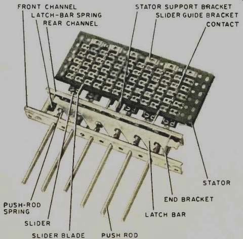
Fig. 1. Array of push-button slide switches, showing terms.
Various electrical parameters of slide switches and the design factors which affect them should be reviewed in the light of two basic trends in switching:
1. Voltage and current requirements are becoming lower and lower. Dry circuitry (with current values less than 50 mA) is gaining favor in communications and electronic data processing.
2. Switches are becoming simpler. With the advent of integrated circuits capable of performing logic functions, switches are needed only to trigger the IC logic circuitry.
The current and voltage range of these switches is from dry circuitry up to either 1 amp at 28 V d.c. or 0.5 amp at 117 V a.c. For higher power applications--2 amps at 28 V d.c. or 1 amp at 117 V a.c. switches with special contacts are available.
The selection of contact base material and plating should be done with several factors in mind: required switch life, type of circuit-inductive or resistive, and environment-temperature, humidity, and presence (or absence) of contaminants.
The following are the most common base material and contact plating combinations for slide switches.
Silver-plated brass with a 0.0001-inch minimum plating thickness will assure silver-to-silver contact for about 10,000 switching cycles. Silver alloy extends the usage to over 200,000 cycles. Both types stand up under 100 °C temperatures.
A special spring-base material with a hard gold alloy rolled on the surface will provide gold-to-gold contact for from 50,000 to 100,000 cycles at up to 150 °C constant ambient temperature.
Hard gold-plated silver alloy (0.0002-inch minimum) will give gold-to-gold contact in excess of 50,000 cycles; and after the gold has worn there will still be silver-to-silver contact with fairly low contact resistance. This combination is usable to 100 °C. Another silver-alloy base with 0.00054-inch hard-gold alloy overlay gives gold-to-gold contact for up to 100,000 cycles and operates at 100 °C constant ambient.
Gold plating is primarily for slide switches used very infrequently since accumulated oxide on a silver contact surface would prevent contact from being made on the first operation. Gold contacts should also be specified for switches in a corrosive atmosphere which might attack silver and for witches used in very low level circuits. Obviously, gold increases the cost of a switch and should be used only where absolutely necessary.
Contact resistance of most low-power slide switches ranges from 0.003 to 0.015 ohm, usually measured from one contact to the adjacent contact. Contact resistance will remain almost constant during rated switch life. However, after the rated life it may change quite significantly. For example, with silver-plated brass contacts, after 10.000 cycles when the silver wears through. brass-to-brass contact will produce increased resistance. With hard gold-plated silver-alloy contacts. resistance will increase only slightly after the rated life of 50,000 cycles.
These life ratings in cycles assume switch usage in low-power circuits. As the amount of circuit voltamperes increases, contact life anti, therefore, switch life decrease. The type of circuit also makes a difference: a low-power resistive circuit produces little, if any, arcing at the contacts, but a highly inductive circuit results in significant arcing which reduces contact life. For circuits with a total inductance of more than a few milli-henrys, designers should choose contact materials with a high life rating.
Silver-plated brass contacts should be used only in low-power resistive circuits to interrupt no more than 1 amp at 28 V d.c. or 0.5 amp at 117 V a.c. Silver alloy and other high-temperature, long-life materials should be used for inductive circuits and higher power resistive circuits to interrupt up to 2 amperes at 28 volts d.c. or 1 ampere at 117 volts a.c.
The breakdown voltage rating of these switches depends primarily on the air between the contacts rather than on the dielectric material used. For the average pushbutton-operated slide switch, the voltage breakdown would be 2000 V between adjacent contacts.
The dielectric almost always used for slide-switch sliders and other insulated parts is high-grade phenolic conforming to MIL-P-3115 specification. Varnishing of the phenolic parts can be specified for contaminated-atmosphere applications. However, this is unnecessary for most slide switches since they are used mainly in commercial applications. In fact, designers of commercial equipment should be wary of specifying varnished phenolics since there is a chance that a bad varnishing job will degrade a good dielectric material and, in addition, destroy the moisture-recovery properties of the phenolic.
Types of Slide Switches
Starting with the simplest type of slide switch, we find it is a button-actuated unit with limited switching action.
This switch, generally UL-rated for 3-amp service, is used as an "on-off" device on communications equipment, stereo and hi-fi units, and instruments.
The next type (see Fig. 2) has far more switching capacity than the simple button-actuated type. With the push-pull mechanism usually actuated by a linear solenoid, its basic application is on printed-circuit boards, since its flat construction makes for easy PC hoard mounting. The same basic switch can also be rotary-shaft actuated giving the user rotary switch action on the front panel and the simplicity of PC board mounting on the rear of the panel.
Push-button-actuated slide switches, usually referred to as merely "pushbutton" switches, are available in either single or multi-button configurations. Maximum switching is 4-pole, single-throw for the simple single-button type.
Basic application for these units and their multi-button counterparts is in communications systems, stereo and hi-fi equipment, and instrumentation.
More complicated switching-up to 12-pole, single-throw per button-can be accomplished with multi-button switches employing larger (and in some cases, double-sided) stators than the single-button units previously described.
These units (a typical one is shown in Fig. 1) give the designer considerable switching flexibility.
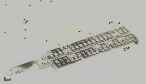
Fig. 2. A 12-pole, 4-throw slide switch for printed boards.
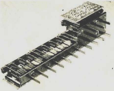
Fig. 3. A second set of buttons may be interlocked with the buttons on the
main switch frame to program the operation.
Mechanical Options
The latch bar is the key to the flexibility and various operating options available in push-button /slide switches.
Its design determines not only what one push rod can do by itself but also the action relationship among several push rods.
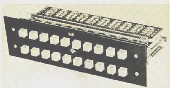
Fig. 4. In this lighted switch, single bulb is used for each group of four
push buttons, reducing lighting cost.
Here is a brief look at the seven basic types of switch operation.
1. Interlock: Probably the most often specified operating method, interlock is accomplished with a common latch bar.
Depressing one button automatically releases any other depressed button. But this does not mean only one button can he pushed at a time. Any number of buttons can be depressed simultaneously. (To prevent more than one button latching at a time. block-out is used.)
2. Release Button: All buttons will remain down when depressed until a release button is depressed. The purpose of this arrangement is, of course, to keep several buttons down at once.
3. Momentary: The latching mechanism may be made inoperative on any of the buttons so that these buttons have an individual spring-return action, independent of any other button.
4. Separate Latching: Push rods are notched so that they hook on the mounting plate when depressed, making each button latch separately from the others. The operator presses in and down to latch the button and runs his thumb along the bottom of the buttons to unlatch them.
5. Double Latch: Two latch bars can operate on the same switch frame with each bar acting on a separate set of buttons. One group of buttons interlocks independently from the other. Double latch is used where maximum switching versatility must be combined with minimum space requirements.
6. Push-Push: Individual latches can be installed on any or all buttons. It permits holding in an "in" position when pressed once. When the button is pressed again, it is released. The remaining buttons on the switch frame can be either interlocking or momentary.
7. Block-out: With this system latching of more than one button at a time is positively prevented. The principal use is in systems where pressing more than one button could cause trouble in critical circuits or, in the case of computer inputs, confuse the logic circuitry.
For a given pushbutton /slide switch the number of buttons with a block-out or the number of momentary action or interlock can vary depending on spacing and other design factors. It is best to check with a switch manufacturer regarding these options.
The latest development in push-button /slide switching is the use of a second set of buttons, interlocked with the button on the main switch frame (see Fig. 3). This second set does not control circuitry as the main frame buttons do, but instead programs the operating method of the circuit control buttons that are used.
Other Mechanical Considerations
After determining the number of individual buttons required and the right combination of operating options, designers should at least be familiar with the length of the stroke and the operating pressure required to actuate the switch.
Usually the stroke of a pushbutton /slide switch is about 1/4 inch. This length is predetermined by the basic design of the switch.
Operating pressure is dependent on the number of contacts per button. Although switch makers have been working to reduce operating pressure, there are still applications where firm pressure is required, such as coin-operated-record players, business machines which handle money transactions, and rugged industrial control systems. Naturally computer input keyboards would require lighter pressure, but most users still want positive "feel" (sufficient pressure to indicate an operation has occurred). Most push-button /slide switches will accommodate an a.c. snap switch on either side of any end button. It will turn "on" or "off" when the button is depressed. Designers should specify whether the button is to be "in" or "out" when the a.c. switch is "off ". These switches, rated at 3 amp at 1N5 V, are usually UL and CSA approved.
Lighting and Lubrication
Lighting is not generally available for single-button slide switches but can be easily applied to multi-button arrays.
One method is to use one bulb behind the panel for each four buttons. Each button has a translucent front and an opaque back so that it is lighted when depressed and (lark when not. This system, used on the switch shown in Fig. 4, greatly reduces lighting cost for the switch array as compared with using a bulb for each button.
Most slide switches are lubricated for their rated life at the factory. It is not necessary for switch users to re-lubricate them. In fact, serious impairment of switch performance can result. Using the wrong lubrication, for example one with electrical conduction properties spilled on the phenolic, could result in a short or excessive leakage between two or more contacts. In addition, lubricating oils used by the factory have been tested over the entire rated temperature range of the switch.
With a basic knowledge of the electrical and mechanical parameters of slide switches, the wide variety available, and the tremendous flexibility ganged push-button-actuated slide switches offer, designers can choose the right one for any application. Also, help in selecting the best switch for the job is always available for any reputable manufacturer.
(source: Electronics World, Oct. 1967)
Also see: Pressure-Sensitive Switches