By MURRAY S. RIFKIN / RETS Electronics Schools
Continuously variable power supply delivers up to 12 volts with a 500-milliampere load.
THIS supply will provide continuously variable voltages up to 20 volts with no load, decreasing to 12 volts with a 500-mA load. Ripple percentage over this range does not exceed 1%, and over a range of 2 to 9 volts, with load currents to 500 mA, output ripple is less than 0.5 %. The power supply is fully protected against damage due to overload by a power-line fuse and a circuit breaker.
The circuit, see Fig. 1, consists of a full-wave bridge using silicon diodes and a large-value capacitor to provide a nominal 20 volts of partially filtered d.c. to the control circuit.
The bridge output is applied to the load through the series power transistor Q1 operating as an emitter-follower and mounted on a heat sink.
Control of output voltage is obtained by varying the series resistance of Q1 which is, in turn, accomplished by varying the base voltage of Q2.
Final filtering without the use of additional filter capacitance is obtained by applying the load ripple voltage to the base of Q2 through coupling capacitor C1. The ripple is amplified and phase inverted by Q2 and applied to the base of Q1 where it is 180° out of phase with the original ripple appearing at the output of Q1. Cancellation of most of the ripple component results in very low ripple output, which is very difficult to achieve in a high-current supply.
Almost any low-level p-n-p transistor may be substituted for the 2N414. Output-voltage drift and ripple percentage may vary with the specific 2N414 selected for use and may vary with substituted transistor types.
The resistance of R1 may require adjustment of value to meet the desired minimum output voltage from the supply (with no load connected) when R2 wiper reaches the end of its rotation movement.
This voltage should be approximately 0.2 volt. If the output reduces to this voltage before full rotation of R2 is reached, the resistance of R1 should be increased. If the output is higher than 0.2 volt at full rotation, the resistance of R1 should be decreased.
The circuit breaker is the type used in TV receivers. It is important that the usual precautions be taken in mounting power transistor Q1. Silicone compound and an insulating washer must be used between transistor and heat sink.
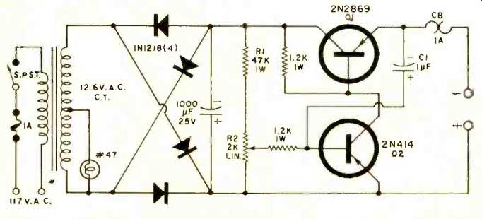
Fig. 1. Schematic of the low-voltage variable power supply.
(source: Electronics World, Oct. 1967)