(source: Electronics World, Apr. 1968)
By FOREST H. BELT / Contributing Editor
Here's the right way to tune color sets along with an explanation of what the controls do. Also covered are circuits that are built in to make tuning easier.
COLOR-TV is about 15 years old and, like most teenagers, it isn't always understood by the adults who live with it. With both, there is a certain amount of adjustment to be made before they work their best. Fortunately, there are definite rules to guide the person faced with developing a working relationship with a color receiver.
Explaining these guidelines is one of the responsibilities of the service technician when he installs the color receiver.
Some do the job well; others either neglect the job or are unable to make the instructions clear. When the job is done right, the owner will know the 1-2-3 procedure that produces a clear and properly hued picture-and every time.
The color tuning procedure isn't really difficult to understand. There are five controls which determine how well the color set renders color. They are: Brightness and Contrast, which also affect the black-and-white picture; Fine Tuning, which affects black-and-white but must be set much more carefully for color; and Hue (or Tint) and Color controls, both used only for color. There is a definite order in which to operate these five controls. Out of sequence, tuning in a really good color picture becomes a haphazard process.
Someone with experience can do it, but for the average color-set owner it may not be so easy.
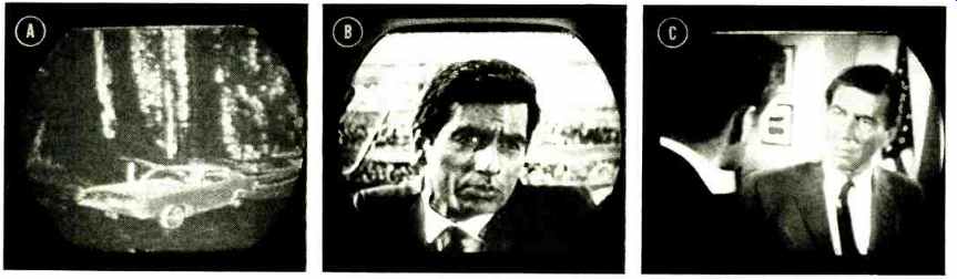
Fig. 1. (A) Severe beat interference. (B) Slight beat interference, (C)
Properly tuned-in black-and-white picture.
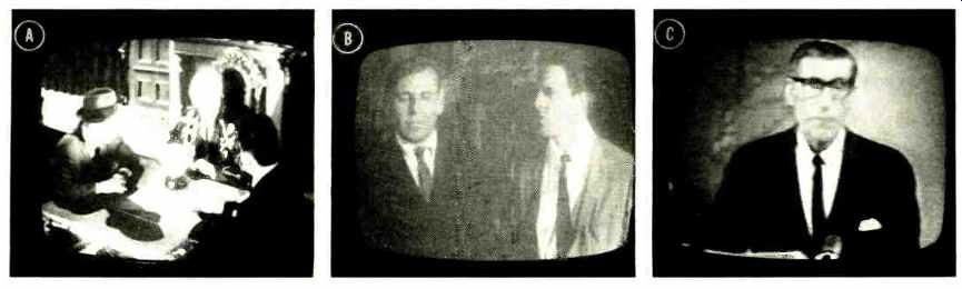
Fig. 2. (A) Excessive brightness and contrast. (B) Insufficient brightness
and contrast. (C) The proper settings.
To understand the color-tuning process thoroughly, you need to know what effect each control has on the picture, on the operation of the circuits in the set, and on one another. You should also be aware of the aids and helps built into many modern color receivers. They take several forms and represent innovative circuits. However, before we get into those, here's the correct way to tune in a color program, and some explanation of what the controls are doing to the set as you operate them.
From Black-and-White to Color
If you're starting from scratch, the best thing is to turn the Color control to minimum (counterclockwise) and the Hue or Tint control to its center. The other three controls can be set best on a black-and-white picture, without color to confuse.
Set Brightness and Contrast arbitrarily at first, so you can see a picture of some sort. Then concentrate on the first and perhaps most important of the five adjustments-Fine Tuning. This operating adjustment is critical; it is the only one of the five that so far has deserved special aids in some of the newer models, and even automatic adjustment in more expensive ones. (The fine-tuning control actually adjusts the frequency of the receiver local oscillator. The effect is to place the received signals properly in the receiver's i.f. hand-pass response curve. -Editor)
First, though, without aids: Turn the Fine-Tuning knob toward the end of its rotation which produces clear sound but a blanked-out picture or severe sound-grain interference such as that shown in Fig. 1A. Then turn it back, almost clearing up the interference grain (Fig. 1B). Interference here is as much a 3.58-MHz beat as 4.5-MHz grain.
It is at this point that the chroma signal and the color-sync burst are tuned in most strongly. But you can't view the picture comfortably with this interference in it, and besides, the video signals are not yet properly located on the receiver band-pass curve. So you turn the control just a little more to rid the picture of the grain-but no further. This is a critical adjustment; make it carefully. When it is done properly, the black-and-white picture should look smooth, as in Fig. 1C. There will be no interference and picture details will be clear.
Next, adjust the Brightness and Contrast. This must always be a compromise between too dark and too light. The usual tendency is to turn the Brightness too high, then make up for it by turning the Contrast well up. Fig. 2A shows the result-a rather garish, harsh picture. Such a picture would never look well when color is added. Rather, keep both the brightness and the contrast as low as possible without washing out the picture. Fig. 2B shows both at too-low settings. Start with them low and work up to a good range of blacks, grays, and whites. Too much brightness will wash out colors and too little contrast will even affect hues. The picture should appear soft, but with good "body ". Fig. 2C shows a picture that will portray color well, when color is finally added.
Now conies the color. Turn up the Color control slowly.
On most sets, it is labeled Color. On General Electric sets it is called Chroma Gain, and Packard- Bell labels it Color Gain; both more aptly describe its action. On Motorola sets, the label Color Intensity is used. The purpose of the control is to adjust the amplification in the chroma-signal amplifier stages, determining how much of the color signal is fed to the demodulators. On the screen, the result appears as intensifying whatever color is visible; that is, the control increases color saturation. This control should not affect the hue of any color; that is, it shouldn't make green turn blue, or anything like that. Turn it up only until you see color.
You'll re-adjust it again after you have made the next tuning in adjustment.
It is the job of the Hue control to make the colors what they should be. The Hue control is called Tint on about half of the most recent models. It could be labeled Color Phase, because it varies the phase of the 3.58 Mhz color subcarrier that is fed to the demodulators for recovery of the chroma signals. Its action is most noticeable in the faces of actors, since the flesh color makes a good reference. With the Color control already set for not-too-strong colors, the Hue control is adjusted for as accurate a flesh tone as you can get. Too far one way makes faces green, and too far the other makes them purple. (One caution: Certain Motorola models have a control called Tint which is not a color-phase control; on Motorola color sets, the color phase is adjusted with the Hue control. This unorthodox Tint control will be explained later.) Next, readjust the Color control for a soft flesh tone, and so that other colors are not garish. Turning the Color control too high may also result in slight interference patterns in the color picture, a pattern that somewhat resembles the grain effect from incorrect fine tuning. A "dead" and faded picture is a sign that the Color control is too low.
The Color and Hue controls should show very little interaction, although the Hue control cannot be adjusted at all unless the Color control is turned up enough to put color on the screen. But, once the Hue control is set, the Color control on most models will not alter the flesh tone-just make it lighter or deeper. If the Color Gain control does affect phase, there is trouble in the set ( usually an alignment problem in the chroma section) which should be cleared up.
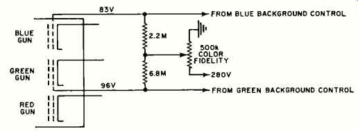
Fig. 3. Putting increased d.c. voltage on the blue and green picture-tube
guns makes the picture take on a brownish color.
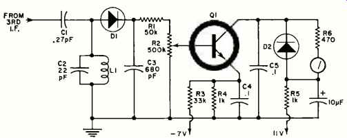
Fig. 4. Tuning meter circuit from one General Electric model.
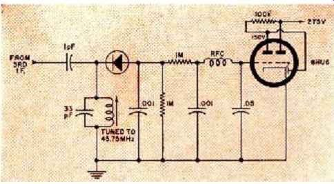
Fig. 5. Target-ray tube used as tuning indicator in a Philco.
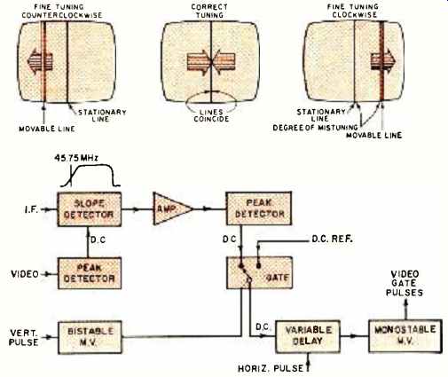
Fig. 6. Westinghouse fine-tuning indicator is probably the most complicated;
uses vertical lines on picture-tube screen.
Auxiliary Controls
On some sets there are two other operating controls which affect the color picture as well as the black-and-white. They are not basically for color reception, but like the Brightness and Contrast they must nevertheless be set properly before a decent color picture can be viewed. Both are most easily adjusted with the receiver tuned to a black-and-white picture. If a color show is on, turn the Color control all the way down to view a monochrome picture.
The first of these auxiliary controls is called a Peaking control, although it has several designations. Clairtone and Magnavox label it Sharpness, Packard-Bell calls it Pix Fidelity, and Setchell Carlson labels it Detail. One older set calls it Crispness. Most others call it Peaking, if they have it. In some, notably Motorola, it is a servicing adjustment rather than an operating control.
It may be a switch and it may be a control, but its purpose is to peak up the high-frequency response of the video amplifier stage and give the picture whites sharper edges.
With a monochrome picture, set the peaking control for a crisp picture, but don't over-peak it. Over-peaking may cause some color "bleed ", particularly in the red; if so, turn it down some for a softer picture. One important point about setting this control: It is for the viewer's taste, so don't set it for a crisp picture unless the viewer wants the picture that way; some prefer softness.
The other control is a sort of "trick" control--sometimes a switch--that lets the viewer make a black-and-white picture take on a sepia or brownish hue. It does this by cutting down the blue and green and stepping up the red coloring of the raster. Before a color program can be tuned properly, this switch or control must be in the normal black-and-white position.
This control carries some undescriptive names. Admiral calls it Color Fidelity, and Fig. 3 shows how it is wired in the CRT circuit. Most others are wired similarly, although a switch may be used instead of a control. Other designations include Clairtone's Colorfast, Hoffman's Cinema, and Magnavox's Chromatone. This is the control that recent Motorola models call Tint instead of using that label for the Hue control.
With these two auxiliary controls in mind, let's review the sequence of tuning in a color picture. First, the Fine Tuning is set for a clear monochrome picture, as near the "sound" end as possible. Then, Brightness and Contrast are adjusted for a soft but clear picture with good grays and blacks. If the set has them, the peaking and brown-shading controls are set for a picture that is sharp and black-and-white. Finally, the color is turned up enough to permit adjusting the Hue control for a good flesh tone, and then the Color control is reset for a picture that shows a good range of color intensity without being gaudy or showing interference patterns.
Of all the operating controls that have to be adjusted to produce an acceptable color picture, experience has shown that the Fine Tuning is the one least likely to be set correctly by the average color-TV viewer. And yet, a wrong setting may prevent color reception altogether. So many of this year's models include one circuit or another to make fine tuning easier. In some sets, they are mere aids; in others, automatic circuits take over and do an accurate job if the receiver is tuned even near a proper setting.
Aids to Fine Tuning
One of the simplest aids to use, at least for many viewers, is a tuning meter. An example is the one used with the General Electric KD chassis. The user merely sets the channel selector to the desired channel and then fine-tunes for a maximum indication on the meter. A diagram of the G-E system is shown in Fig. 4.
All of the fine-tuning aids and automatic circuits use the same basic principle: tuning the receiver oscillator so that a precise 45.75-MHz video i.f. signal is produced. A very small capacitor, C1 in Fig. 4, couples a sample signal from the third i.f. stage to a 45.75-MHz tuned circuit, C2-L1.
Diode D1 rectifies the sample signal, and R2 feeds a certain amount of the resulting d.c. to the base of Q1, a d.c. amplifier. Conduction of Q1 determines how much current flows in the meter, which is in the collector circuit. As the fine tuning control moves through the "best" 45.75-MHz point, the signal developed across tuned circuit C2-L1 goes through a peak. The resulting maximum of d.c. developed by D1 is passed on to Q1 and the meter registers a collector current peak. C3, C4, and C5 help keep the video signal from reaching the meter and making it "wiggle" with changes in scene brightness. Diode D2 damps the meter, making it easy for the viewer to see a true peak.
Philco and Andrea use a system that is similar, except that a tuning-bar tube is used instead of a meter. The Philco circuit is shown in Fig. 5. Again, a tuned circuit senses when the most 45.75-MHz signal is being produced by the tuner. The signal is rectified and filtered and the resulting d.c. applied to an indicator--in this case, a 6HU6 shadow-bar tube. A dark "bar" appears against a lighter background and it becomes narrowest when the most d.c. voltage is applied to its input or control grid. Since maximum d.c. is developed when the oscillator fine tuning is permitting the most 45.75-mHz signal, the narrowest bar indicates optimum fine tuning.
Motorola uses a slightly different form of indication, although the principle of producing it is the same. Instead of indicating when fine tuning is correct, the Motorola system causes a lamp to glow when tuning is incorrect. A 45.75MHz tuned circuit and a transistor work exactly as with the G-E system already described. The d.c. "peak" is coupled, instead of to a meter, to a switching transistor that extinguishes a lamp when the set is fine-tuned for maximum 45.75-MHz i.f. signal. If the tuner drifts, the lamp lights, signaling the viewer that the fine tuning needs touching up if a proper color signal is to be received.
Westinghouse uses a still different form of indication for its fine-tuning indicator. The viewer can pull a switch and a vertical bar (or two) appears on the screen. If two bars appear, it is an indication that the set must be fine tuned.
When the two coincide, the 45.75-MHz signal is at its peak in the i.f. strip, which means the fine tuning is correct.
Producing the Westinghouse indicator pattern is more complicated than any of the others. Fig. 6 will help you understand how it is done. One of the vertical lines, the stationary one, is produced by "marking" the midpoint of each line during one vertical field; thus, 262 of the raster lines carry the video pip that produces the stationary vertical line which serves as the tuning reference. Its position on the screen is determined by a fixed d.c. reference voltage.
The movable tuning line is the result of video pips on the other 262 lines, during the alternate vertical field. Its position is determined by a voltage from the detector circuits, which sense the frequency of the 45.75-MHz i.f.
The detector circuits aren't as simple as those in other fine-tuning aids, either. Instead of sensing the peak, the system senses when the 45.75-MHz signal is at a particular point on the slope of the detector curve. The first peak detector uses the strength of the video signal to counteract effects of weak signals which might otherwise produce false indications from the slope detector.
The output of the slope detector is a steady video signal whose strength depends on correct tuning. The second peak detector rectifies that signal and produces a d.c. voltage that sets the position of the movable video pips on each alternate horizontal line of the raster. (A complete description of this circuit and its servicing adjustments can be found on page 68 of our December 1967 issue.)
Fine-Tuning Automatically
Besides these manual aids, there are automatic fine-tuning systems, which were described in some detail in the January 1968 issue (page 41). Their operation is two-fold: a 45.75 MHz sensing circuit very much like those used for manual fine-tuning indication; and a tuner whose tuning can be affected by a d.c. control voltage developed in the sensing circuit. Basically, an automatic fine-tuning circuit senses when the local oscillator drifts off frequency enough to reduce the 45.75-MHz signal sensed by the a.f.t. circuit, then produces a d.c. correction voltage which is applied to the tuner to pull the oscillator back on frequency.
Fig. 7 shows the system in simplified block form. Tubes have been used, although most recent models use transistors. You'll even find integrated circuits in the a.f.t. stages of a few models-notably Clairtone, RCA, and Zenith. Most models apply a.f.t. to both u.h.f. and v.h.f. tuners. A backward-biased capacitance diode completes the tuning circuit in the oscillator. The d.c. correction voltage from the a.f.t. discriminator shifts the capacitance in whatever direction is needed to bring the oscillator back to correct frequency so a precise 45.75-MHz video i.f. is produced.
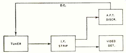
Fig. 7. Closed loop that forms automatic fine-tuning system.
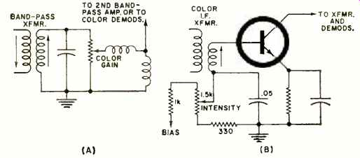
Fig. 8. Typical color controls. (A) Most popular one acts like a color "volume
control ". (B) One that controls bias.
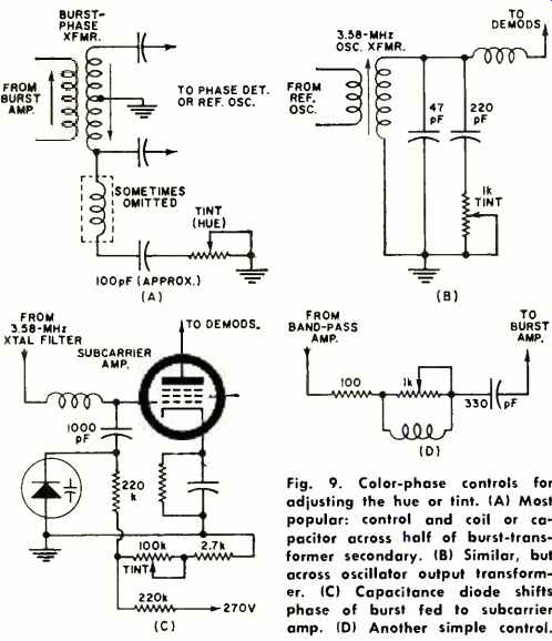
Fig. 9. Color-phase controls for adjusting the hue or tint. (A) Most
popular: control and coil or capacitor across half of burst-transformer
secondary. (B) Similar, but across oscillator output transformer. (C)
Capacitance diode shifts phase of burst fed to subcarrier amp. (D) Another
simple control.
The correct procedure for fine-tuning a color receiver that has a.f.t. is the sane as for any other, except that the a.f.t. must be defeated during the fine-tuning process. In some tuners, the a.f.t. is automatically disabled when you push in the fine-tuning control to tune it; others have an a.f.t. defeat switch which must be set in the "a.f.t. defeat" or "a.f.t. off" position.
The knob is tuned just as described earlier, first for best sound with no picture and then for a good picture as near "best sound" as possible. After that, reactivate the a.f.t. and it will hold the tuner precisely on frequency. The fine tuning should be set individually for each active channel, then it seldom needs resetting thereafter. Don't disturb this setting unless there is reason to believe the tuner has, over a period of time, drifted beyond the influence of the a.f.t. circuit. (One Motorola model includes a fine-tuning indicator in addition to the a.f.t. circuit; a warning lamp glows if there is excess drift.) Color and Hue Controls Chroma controls haven't changed much over the past few years. Their place and function in the circuit have been much the same for some time. If you've seen many color TV sets, you're already familiar with the popular arrangement in Fig. 8A. The control is merely a "volume control" following one band-pass amplifier (color i.f., Motorola calls it). In some models, another band-pass amplifier follows the control; in others, the demodulators. Motorola, which calls this control the Intensity control, places it in the cathode circuit of one color i.f. ( band-pass) amplifier, a cathode-follower that drives the following stage. In the new Motorola transistor color receiver, the Intensity control is a potentiometer that sets the d.c. bias of one color i.f. amplifier ( Fig. 8B) . Zenith, in a tube model, also uses a bias control pot for controlling chroma gain; they place it in the cathode circuit of one band-pass amplifier (which the Zenith schematic calls a color amplifier). Phase controls, too, aren't much different from those in use several years ago, although there is a wider variety of circuit schemes. The basic purpose of the Hue or Tint control is, ultimately, to affect the phase of the reference (3.58-MHz) signal fed to the demodulators, which affects the angle of demodulation and thus the hue of the signals applied to the CRT guns. This can be done by altering the phase of the color-sync (burst) signal before it reaches the reference oscillator, or by altering the phase of the reference signal after it is generated but before it reaches the demodulators.
Both methods are used, but the former is the more popular.
The basic circuit arrangement in Fig. 9A is common to Clairtone, Hoffman, Magnavox, Motorola, Packard Bell, Philco, Setchell Carlson, and Zenith. In some of them, only the capacitor is used, without the extra inductance; in Zenith, only a potentiometer is used. Varying the potentiometer setting introduces more or less of the effect of the capacitor (or coil-capacitor) across one winding of the burst transformer, shifting the phase of the burst signal that is passed on to the phase detector. This, in turn, controls the reference oscillator phase. In the Zenith, the pot alone merely unbalances the winding and thus alters phase.
A similar arrangement (Fig. 9B) , except that it is in the reference-oscillator output transformer circuit, is used in Admiral and many RCA models. The pot and capacitor are across the winding, but interact with the inductance that follows.
One recent G-E model uses something entirely different, although its purpose and result are the same. Fig. 9C shows the arrangement; a biasing potentiometer that varies bias on a varicap diode in the special subcarrier amplifier circuit that G-E uses instead of the more common controlled oscillator. The stage amplifies the incoming 3.58-MHz burst, which arrives through a 3.58-MHz quartz-crystal filter, then feeds its phase-locked output to the demodulators. The variable-capacitance diode controls the phase of that output, depending on the bias set for it by the potentiometer.
Recent Arvin sets are different, too.
Phase is controlled in them by the very simple device shown in Fig. 9D--a coil-capacitor combination, in series, preceding the burst amplifier. A potentiometer across the coil is the means for varying the phase shift introduced by the network. Simple, but effective.
There are minor variations of these Color and Hue controls from model to model, but most Hue controls resemble one of those we have already discussed.
Striving for Perfection
To further simplify color-TV tuning for viewers, manufacturers have attempted to make the control of color and phase more and more "automatic ". To some small extent, they have succeeded. Many chassis have what are called automatic color control (a.c.c.) and automatic phase control (a.p.c.) or automatic frequency and phase control (a.f.p.c.) . However, they are automatic only in the same sense that automatic gain control (a.g.c.) is automatic, not in the absolute sense that automatic fine tuning (a.f.t.) is automatically accomplished.
Automatic color control is merely an "a.g.c." for the band-pass amplifiers. If the color signal weakens, the gain is raised slightly; if it becomes so strong that it makes the colors on the screen too harsh, the gain is reduced by the a.c.c. circuit. The result is a fairly stable color saturation level, that is, the system can maintain the color at what ever level is set by the viewer with the Color control.
The terms a.p.c. or a.f.p.c. are merely names for the circuit that applies color sync to the color reference oscillator. True, its job is to keep the oscillator in exact phase, but that phase still depends on the incoming color burst. The " automatic" action is not sufficient to overcome the phase differences that so often occur from camera to camera, from program to program, and from station to station. For that reason, viewers must still get up and alter the setting of the control several tunes (luring an evening of color viewing. Thus far, no manufacturer has perfected an a.p.c. circuit with sufficient range or adequate sensitivity to pull the oscillator into phase automatically in such cases-advertising claims not withstanding.
Thus, perfection is still unattained.
Step by step, though, color-set manufacturers are licking each problem.
Only three years ago, one of the toughest problems of the color television installer was to teach the viewer how to make sure the Fine Tuning was correct for watching color; now there's a.f.t.
Rest assured that it won't be long until every single control on a color set can be preset and will then operate automatically. Even the presetting will be handled by aids of the type used now only for the most troublesome adjustments.