By DAVID L. HEISERMAN
Microminiature ceramic and tantalum chip capacitors, no bigger than match heads, are available for use on hybrid IC's. Design parameters and comparative characteristics are covered.
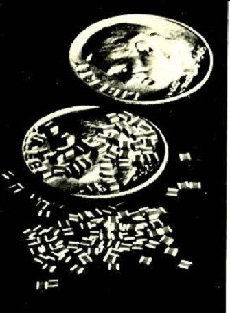
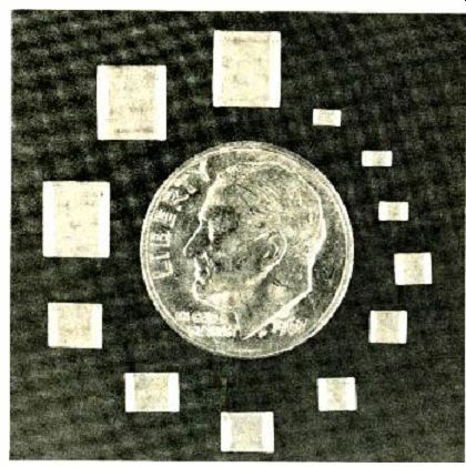
A group of ceramic chip capacitors, showing their small size.
CAPACITANCE
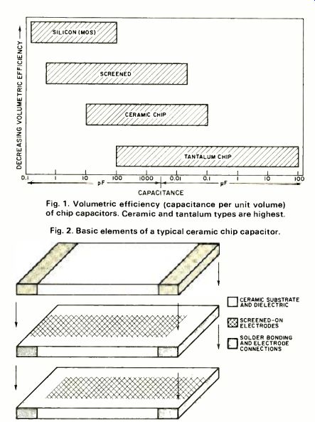
Fig. 1. Volumetric efficiency (capacitance per unit volume) of chip capacitors. Ceramic and tantalum types are highest.
Fig. 2. Basic elements of a typical ceramic chip capacitor.
INTEGRATED circuits are tributes to modern research and production ingenuity. Today it is not only technically possible, but economically feasible to put a hundred or more transistor structures onto a single silicon chip no larger than a match head. Even with this remarkable talent for producing microscopic and complicated active structures growing every day, no one has yet figured out a way to integrate a common passive capacitor larger than 100 pF onto a transistor-ladened chip.
Whenever circuit designers want to add a capacitor to an IC, they have to solder it in externally. Until recently, a single external capacitor took up more space on a printed-circuit board than a hundred integrated transistors and resistors. Capacitor manufacturers have joined the rush to microminiaturization, though, and it is now possible to buy reliable monolithic (single-chip) capacitors in the 100-pF to 1-uF range that are no larger than a match head. These chips are still add-on devices, but many are so small that several can fit into a package with an active IC chip.
Standard chip capacitors have package configurations that make it easier to solder or weld them into hybrid microcircuit packages. Some have dabs of solder on each end instead of the traditional wire leads. A hybrid circuit manufacturer, then, can solder the capacitor terminals to a bonding pad by means of a solder reflow technique. Other kinds of chip capacitors have a dab of solder on one end and a short lead on the other. At a customer's request, chip capacitor manufacturers can also place long leads on both ends, dip the assembly into epoxy, and sell the chip as a standard microminiature discrete capacitor for PC-board mounting.
Volumetric Efficiency
The most important chip capacitor design parameter is that of volumetric efficiency (capacitance per unit volume).
Fig. 1 shows the volumetric efficiency of four chip capacitor compositions as a function of capacitance.
Silicon chips have the least volumetric efficiency and the lowest capacitance values. Since they can be integrated directly onto an MOS integrated circuit chip, there isn't much call for single-chip versions, anyway. A typical MOS chip capacitor has a tolerance that runs anywhere between 100 and 200 percent. This limits their use to simple bypass applications where tolerance isn't a critical factor.
Modern thick-film technology makes it possible to produce capacitors by screening alternate layers of conductive and dielectric inks onto a substrate material. These so-called "screened" chip capacitors can compete with ceramic and tantalum chips up to about 10 pF. This competition, however, is only by default. Present-day dielectric inks have relatively low dielectric constants, so screened chips are bound to have lower volumetric efficiencies. It is only the fact that 10 pF is the smallest ceramic chip on the market that makes screened chip capacitors competitive in lower ranges.
Ceramic and tantalum chip capacitors are, by far, the most popular chip capacitors on the market today. Looking through the mass of literature on chip capacitors, one might even get the impression there are no other kinds available.
Just like screened capacitors, ceramic chip capacitors have a thin layer of screened-on conductive ink for electrodes (Fig. 2). Instead of a dielectric ink, however, ceramic chips have a thin layer of ceramic material between the electrodes. Ceramic materials can have a dielectric constant (K) two or three orders of magnitude greater than the best dielectric inks. This accounts for the higher volumetric efficiency of ceramic chips.
Tantalum chip capacitors have the highest volumetric efficiency of all, and the highest and widest range of capacitance values. A 68-µF Union Carbide (Kemet) tantalum chip rated at 4 w. V d.c. measures only about a quarter-inch square and an eighth of an inch thick. The secret of tantalum chips' volumetric efficiency is the fact that they are actually microminiature electrolytic capacitors.
Traditional circuit designs make capacitors in the 100-pF to 10-µF range the most popular values. Available ceramic and tantalum chip capacitors have values that overlap in this popular range, so there is a great deal of competition for the market. Some manufacturers have thrown their lot with one kind of chip capacitor or the other exclusively.
Aerovox, Centralab, Republic Electronics, San Fernando, and Vitramon, for instance, produce only ceramic chip capacitors. Mallory, on the other hand, is one company that produces tantalum chips exclusively. Other companies, such as Union Carbide and Sprague, supply both markets with lines of ceramic and tantalum chip capacitors.
Although volumetric efficiency is a prime chip-capacitor design parameter, it is not always the first thing circuit designers consider when selecting chip capacitors for a particular application. Tantalum and ceramic chips both have ...
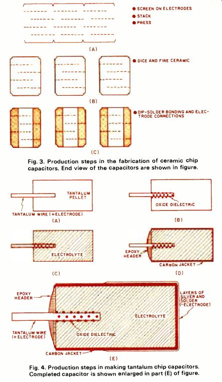
Fig. 3. Production steps in the fabrication of ceramic chip capacitors.
End view of the capacitors are shown in figure.
Fig. 4. Production steps in making tantalum chip capacitors. Completed capacitor is shown enlarged in part (E) of figure.
... their own advantages and shortcomings. An understanding of how they are made points up their merits and drawbacks.
Manufacturing Chip Capacitors
The ceramic chip capacitor production process begins with several large, thin slabs of unfired ceramic (Fig. 3). A thin coating of conductive ink is screened onto the slabs, then they are aligned and stacked to form alternate layers of ceramic and electrode material.
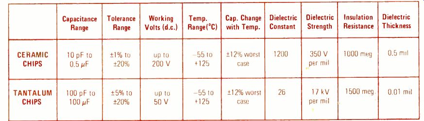
Table 1. Comparison of some of the essential characteristics of ceramic
and tantalum chip capacitors.
--- Ceramic chip capacitors come in larger sizes too. The light patches
on ends of the chips are solder terminals.
A precision pressing operation squeezes the stacks to-gether to form the desired dielectric thickness. Ceramic technology has advanced to the point where it is possible to squeeze the stacks to get dielectric thicknesses of less than 0.5 mil.
After they're pressed, the ceramic slabs can be diced into individual chip capacitors and fired in an oven at about 2600 °F. The only step that remains, then, is silvering and dip-soldering each end of the capacitors.
This dip-solder process electrically connects alternate electrode layers together to form the equivalent of several capacitors connected in parallel. The metal coatings also serve as bonding terminals.
The manufacturing process for tantalum chip capacitors is much more involved. The first step consists of compressing a bit of high-grade tantalum powder into a pellet of the
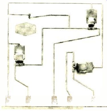
There are four tantalum chip capacitors soldered to
PC board.
desired size and shape (Fig. 4). A typical pellet for a 1 uF tantalum chip measures about 0.15 inch square and 0.05 inch thick. A piece of AWG # 24 tantalum wire is pressed into the pellet during the compression operation. This wire later serves as the positive terminal.
An anodic process forms the dielectric layer around the tantalum wire. This layer of dielectric material, tantalum pent-oxide, is often as thin as 0.003 mil. The dielectrics in some tantalum chips manufactured by Mallory are so thin they can be measured in angstroms-a unit generally reserved for measuring wavelengths of light.
Since tantalum chip capacitors are actually microminiature electrolytics, the pellet has to be impregnated with an electrolyte, such as manganese dioxide. This electrolyte is the true negative terminal of the capacitor.
Once the electrolyte has formed, the pellet is coated with a protective jacket of conductive carbon. The carbon jacket itself gets a thin coating of silver and ordinary 60/40 solder.
Since all three of these materials are good electrical conductors, they form a negative terminal surface that can either be welded or soldered directly to the microcircuit bonding pad.
A blob of epoxy around the tantalum wire-the positive terminal of the capacitor-strengthens the connection and insulates it from the conductive materials that make up the negative terminal.
Ceramic versus Tantalum
Table 1 compares some of the essential characteristics of ceramic and tantalum chip capacitors. These figures mainly reflect the quality of the dielectric material.
The volumetric efficiency of ceramic chip capacitors depends upon the extraordinarily high dielectric constant of modern ceramic materials, especially those containing barium titanate. The K value for most ceramic materials lies between 1000 and 6000, but a few high-performance chips use ceramics having K values as high as 13,000. By comparison, conventional capacitor dielectrics, such as mica and aluminum oxide, have K values of less than 15.
The dielectric constant of tantalum compounds is only about 26. This means that tantalum chip capacitors cannot rely upon the dielectric constant for their superior volumetric efficiency. The value of any given capacitor, however, is both a function of the dielectric constant and the thickness of the dielectric material itself. Increasing the volumetric efficiency of any capacitor, then, is a matter of increasing the K value of the dielectric material or decreasing the dielectric thickness. Tantalum chip capacitors depend on the latter technique for their very high volumetric efficiency.
For example, Table 1 shows that a typical ceramic dielectric has a K value about 50 times greater than the tantalum versions. To more than make up the difference, tantalum chip capacitors of the same value and voltage rating have a dielectric material that is 50 times thinner. These ratios change considerably with different capacitance values and voltage ratings, but the ratios always favor the tantalum chips.
Tantalum chip capacitors suffer the same disadvantages inherent in most electrolytics-polarized terminals and relatively low working voltages. Accidental voltage reversal on a tantalum chip can change the value of the capacitor, reduce its breakdown voltage, or increase its insulation leakage. At worst, a reverse voltage can destroy the dielectric altogether, so hybrid microcircuit engineers must abandon tantalum chips and use ceramics wherever there is a possibility of voltage reversals.
An inherently low capacitor working voltage is not the serious disadvantage it used to be. Except for high-voltage power circuits, there is virtually no need for capacitors with voltage ratings in excess of 50 volts. Hybrid microcircuits, the home of most chip capacitors, operate in the 6-, 12-, or 24-volt range, anyway.
Ceramic chip capacitors, as simple as they are, are susceptible to hazards even more difficult to track down than accidental reverse voltages. Barium titanate additives contribute many of the problems of ceramic chips. For one thing, the electrical characteristics of barium titanate change after being subjected to temperatures in excess of 125 °C. Although ceramic chips are not supposed to be polarity sensitive, it is possible to accidentally polarize them if they happen to hold a small charge when bonded into a circuit with a high-temperature soldering process. Later on, such capacitors appear to have one value when charged with one polarity and quite a different value when charged with the opposite polarity.
Barium titanate is also a piezoelectric material that causes the value of a chip capacitor to change with mechanical distortion or pressure. Manufacturers, then, have to trade off high-K barium titanate additives for better temperature and stress specifications.
In spite of these problems with ceramic chips, it is possible to construct NPO (zero temperature coefficient) ceramic chip capacitors. Such capacitors have K values less than 20, but ceramic chips can afford this further loss of volumetric efficiency because tantalum chips cannot have an NPO characteristic at this stage of development. Until recently, NPO capacitors with values above 500 pF were unheard of. Aerovox, though, is one company now producing NPO ceramic chip capacitors above 1 uF. In general, tantalum chip capacitors are less expensive than the ceramics. A tantalum chip capacitor that costs 75 cents may have a ceramic counterpart that costs over a dollar. The manufacturing process for ceramic chips is much simpler than the tantalum process, so the higher cost of ceramics is not due to manufacturing techniques. The higher cost of ceramic chips can be attributed to the cost of metal alloys used as electrodes between the dielectric layers. These alloys have to be of noble metals such as palladium and platinum.
Less expensive metals corrode or break down after the high-temperature ceramic firing process.
Ceramic chip capacitor manufacturers are attempting to develop "cold" ceramic firing processes that will eliminate the need for expensive noble metal alloys. Until this process is perfected, sheer high volume production is the only way to make ceramic chips costs more competitive with tantalum.
Also see: EW Lab Tests -- Dynaco, Wollensak