By MILTON S. SNITZER / Technical Editor
Answers to questions being asked about the operation of this fully compatible, four-channel stereo system.
SINCE the appearance of our September article "The Scheiber 4-Channel Stereo System," a number of questions have come up on the operation and performance of the system. Our article showed the equations used in the matrixing sections of the encoder and decoder (see Fig. 1). Some readers have found that these equations raised more questions about the system than they answered.
For example, if you substitute the numerical values of the four separate channels that are matrixed into Scheiber's two (A and B) channels in the playback decoder, here is what you find. When there are equal signals on all four input channels, the signal fed to the front left (FL) speaker after matrixing consists of 100% of the FL signal plus 70% of front right (FR) signal plus 70% of rear left (RL) signal plus none of the rear right (RR) signal. Under these same conditions, the signal fed to the front right (FR) speaker consists of 100% of the FR signal plus 70% of FL signal plus 70% of RR signal plus none of the RL signal. A similar analysis holds for signals applied to the other two speakers.
According to these figures, the channel separation would be only 3 dB; that is, signals from adjacent channels are down only 3 dB or 70% of the desired signal. However, bear in mind that when the signals are similar in all four channels and all four speakers are reproducing the same information, there is little or no need for channel separation.
Next, consider what happens when there is signal in only one channel. Assume our original program consists of information in the front left (FL) channel only. Again, using the matrix equations and noting that all terms except FL drop out, here's what happens after matrixing in the decoder.
There will be a 100% FL signal and nothing else in the FL speaker. At the same time the FR and RL speakers will carry 70% of the FL signal, and the RR speaker will carry none (0 %) of the FL signal. Notice how the matrix arrangement groups the four speakers into two sets of diagonally opposite pairs.
Now here is where the gain-sensing circuits, employing the IC differential amplifier, come into the picture. When these circuits sense the difference between the 100% and the 0% FL signals in this example, they increase the gain of this pair of diagonal channels (FL and RR) and, at the same time, they turn off the opposite diagonal pair of amplifiers (FR and RL) which had been carrying the 70% FL signals.
As a result, separation, or more exactly "isolation," goes way up. The only limitation now is the inherent crosstalk between the channels, which can be made very small. The same type of analysis holds true for the four channels when any one of the other three contains information.
If the difference between the two signals in the opposite-corner amplifiers is less than the 100% to 0% ratio, then the relative gains of the four channels are adjusted between the above limits. In practice, then, the amount of separation varies with signal content. The more similar the signals are in all four channels, the less will be the separation. Average values of 15 dB or better are readily obtained with most program material. Hence, in return for being able to combine four channels into two, the Scheiber system trades off channel separation.
There are still some unanswered questions about the system, since full details have yet to be released. For example, do the gain-sensing circuits work only on amplitude differences or can they adequately take into account the differing frequency and phase content of the signals being compared? What if you had a violin in one channel, a piano in the second, a clarinet in the third, and a flute in the fourth-all at exactly the same amplitude? Would the system be able to compare them and retain a high degree of separation between the channels? Circuits can be designed to make this type of comparison but they are not simple. In any case, the Scheiber system is an important "first" and is well worth watching.
More on the
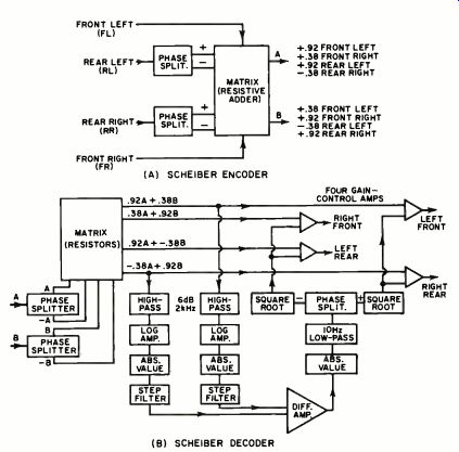
Fig. 1. Block diagram of encoder and decoder repeated from September issue.
Encoder is installed into phono or tape mastering system or in broadcast
transmitter. The decoder is inserted in the playback system where
it is located between the output of a two-channel preamp and a four-channel
power amp and speakers.
Also see: