By EUGENE LEMKE /Manager Color-TV Engineering, RCA
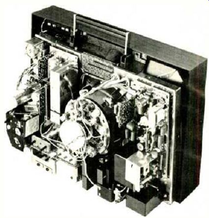
--- Rear view of CTC-49 chassis with all modules plugged in.
RCA's new CTC-49 solid-state chassis represents the greatest single departure for the company from traditional techniques.
Plug-in modules, thick-film ceramic circuits, and a new wide-angle picture tube are featured.
THE new CTC-49 solid-state color-TV chassis represents perhaps the greatest single departure by RCA from traditional circuitry and techniques. The primary purpose has been to reduce the total circuit to small, easily identifiable, independently aligned and, therefore, totally interchangeable functional modules.
A number of significant factors have influenced the ultimate decision as to what circuits should constitute an integral module and the total number of modules that should be used in a color receiver. The modules must maintain a minimum identifiable performance function so that one can readily isolate a defective unit by certain performance deterioration or malfunction, thus reducing some of the skill required in servicing. At the other extreme, the module should not become so large as to burden the user with ...
--------
What Does it Mean to the User?
RCA's modular approach to color-TV circuitry, as exemplified by the CTC-49 chassis (Argosy-Model EP-506), is a major step toward "instant replacement" servicing in the home by the technician of vital circuit components. Just as the older tube sets could be serviced by tube replacement in the home, in this new receiver, the solid-state plug-in modules are readily replaceable.
The chassis employs eleven plug-in "AccuColor" circuit modules, including three ceramic circuits, five silicon integrated circuit chips, and an easily replaced tuner assembly.
All of the plug-in modules are covered by the company's warranty program for a period of one year from original purchase of the set. The user has the option of selecting the service agency. RCA Service branches will maintain an inventory of all the various plug-in modular units. Independent service technicians will either maintain a similar inventory or be able to obtain replacement units through the nearest RCA branch.
A national network of regional offices is being set up to implement this program and make replacement modules readily available at the consumer level. The regional offices will be supplemented by district offices in key cities across the country.
Initially, circuit modules will be replaced under the warranty program by new factory units. Eventually, the program will involve replacement by factory-rebuilt units under the same sort of set-up that prevails in the automotive and other con sumer businesses. The most obvious advantage to the con sumer is a far higher percentage of "in-home" servicing, resulting in faster and less-expensive repairs.
----------------
... excessive replacement costs. In fact, the user cost should be low enough to preclude the repair in favor of replacement.
Additional size limitations are imposed by considerations of interaction of circuits, radiation, and capacitive limitations in high-gain, high-frequency circuits.
Long-term goals have to be taken into account when designing modules in order to provide for improved techniques in the future, while retaining the same module terminal technique. Already the extensive development of specialized monolithic and ceramic circuit techniques for color TV have had significant influence on module design.
The CTC-49 features a total of eleven pluggable circuit modules (shown in color, Fig. 1). All modules are positioned in the chassis to face rearward and are easily and independently accessible for removal. Except for the low-voltage power-supply module, the rest are plugged into phenolic master boards utilizing specially designed edge connectors.
(Editor's Note: Refer to our lead photo for a rear view of the chassis with the modules plugged in. This is shown in color un our cover, along with an extra set of the plug-in modules.) The whole TV chassis can be considered to be divided into five distinctive assemblies, as follows: (1) The tuner assembly contains both the v.h.f. and u.h.f. tuners which are both automatically fine-tuned, as well as the primary customer controls-color, tint, brightness, on-off, volume, a.f.t.-defeat switch, and continuously variable sharpness control. The total assembly can be easily removed through plug connectors. (2) The complete signal-processing assembly (Fig. 2), consisting of one master board and eight modules. (3) The deflection master board with its vertical and horizontal oscillator function modules (Fig. 3). (4) The chassis proper, on which the miscellaneous heavier components are assembled. These include the low-voltage transformer, deflection output devices and their heat sinks, solid-state high-voltage quadrupler, and a small auxiliary circuit board containing picture-tube set-up controls and the less-used horizontal hold, vertical hold, and contrast controls. (5) The remaining assembly constitutes the picture tube itself, its deflection and convergence yokes, convergence wave-shaping circuitry and its controls, purity and blue lateral assembly, and degaussing shield and coil.
Here is a brief description of the chassis circuitry. high-lighting the most important differences compared to previous receivers.
The tuner assembly follows very closely the practices employed in the company's previous solid-state chassis. It uses a four tuned circuit wafer switch v.h.f. tuner with MOSFET r.f. amplifier, a cascode-type mixer and a.f.t.-controlled local oscillator. Most significant variation is the elimination of the familiar "link circuit." In its place is a terminated coaxial line which interconnects the tuner and the i.f. amplifier input independent of each other and the length of the interconnecting cable is no longer critical. This results in total interchangeability of the tuner and i.f. assemblies without requiring subsequent realignment of tuned circuits as has been the case in the past.
The total signal-processing circuitry is connected from the tuner-assembly output to the picture-tube socket. Five monolithic integrated circuits are used, replacing a substantial number of discrete circuit components. The pix i.f.-a.f.t. module is completely self-contained, and the heart of the module is a new complex integrated circuit specifically designed for this purpose and used for the first time in TV receivers. This IC performs the total amplification at the picture i.f. passband, with outputs for the 4.5-MHz intercarrier sound signal, low-level video, and color information.
Another output provides reference for the now rather conventional automatic fine tuning (a.f.t.) integrated circuit, which is also contained on this module.
The video output from the i.f. module is fed into the video /sync module. The functions of luminance delay, vertical and horizontal retrace blanking, control of contrast, and control of video peaking are performed in the first video amplifier transistor. The second video amplifier is an emitter-follower stage which provides an impedance match between the first video amplifier and the three parallel-driven picture-tube drive modules.
The tuned color input is fed into the first chroma module.
As is the case with the pix i.f. module, a specialized IC has been developed for this circuit and used for the first time.
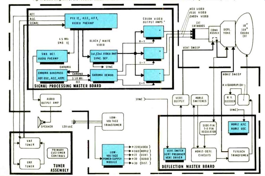
Fig. 1. Block diagram of the receiver which consists of five main assemblies
that include eleven plug-in modules (in color).
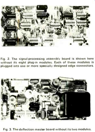
Fig. 2. The signal-processing assembly board is shown here without its eight plug-in modules. Each of these modules is plugged into one or more specially designed edge connectors.
Fig. 3. The deflection master board without its two modules.
All active devices in this module are contained in this single IC, which serves as a chroma bandpass-amplifier, burst amplifier, and reference oscillator, as well as performing the a.f.p.c., a.c.c., color-level, control, and burst-blanking.
The 3.58-MHz output from the first chroma module is then fed to the second chroma module, which contains the chroma demodulator and color difference amplifier functions. Again, a unique IC is utilized.
So far the chroma video system has borne at least some resemblance to circuits used in the past. The output of the chroma demodulator, however, consists of three color-difference signals, R-Y, B-Y, and G-Y, which are fed into three identical and corresponding picture-tube drive modules in which the matrixing of luminance and chrominance video is now accomplished ahead of the picture tube itself. The resultant output is used to drive the corresponding picture-tube cathodes. Note that we are using three medium-power devices in parallel as compared to one high-power video-output device and three separate picture-tube control-grid drivers.
The sound module is identical to one currently used in other RCA color receivers and requires no further comment.
This, then, represents the entire signal section and, with minor value changes in signal-board components, it can be used with any picture-tube combination.
The picture-tube drive modules represent the first application of thick-film technology to color receivers. This allows bulk production of discrete components by chemical means directly on a ceramic substrate. Due to good thermal characteristics, the transistors that are bonded directly to the substrate require no further heat sinking with a resultant package that is small, simple, and offers good long-term economic advantages.
Wide-Angle Picture Tube
The deflection and picture-tube assemblies represent another major advance. The CTC-49 is the first domestic receiver utilizing the new 110° wide-angle deflection picture tube as compared to a more common 90° deflection angle tube. This results in a substantially reduced depth in the over-all package. For the first time an 18-in color receiver is available on the market that has the slim appearance of comparable black-and-white television sets.
The horizontal-deflection circuitry itself bears close resemblance to the circuitry used in the company's CTC-40 chassis. Outside of parameter and component adjustments and modifications to provide for the substantially increased deflection power and increased raster pincushion distortion requirements, it does not differ greatly in operating principle. Noteworthy is the use of a high-voltage multiplier, which requires only one-fourth the voltage input to provide the picture-tube high-voltage requirements.
The vertical and convergence circuits represent substantial departures from previous practices. The usual vertical-output transformer has been eliminated through use of a complementary-symmetry output circuit, similar to that used in high-quality, high-power audio systems. The vertical-convergence waveforms are clamped at deflection center, resulting in substantial reduction in the interaction of the individual wave-shaping controls.
The CTC-49 represents a potential building block for future sets and provides means for substantial standardization of circuit modules. It indicates the expanded use of linear monolithic integrated circuits custom-tailored to unique color-TV needs. It also opens the door and gives us a glimpse of the future through use of ceramic circuits, wide-angle deflection CRT's and other circuit innovations.
Also see: Test Equipment Product Report
New Color-TV Kit, William Stocklin