By KURT T. RUDAHL
An accurate a.f. generator, providing resettable, sine-wave audio signals, made from inexpensive IC and transistors.
Author's generator was built into small chassis box. Three controls at left set frequency to two significant figures plus multiplier. The controls at right determine the output level.
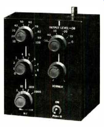
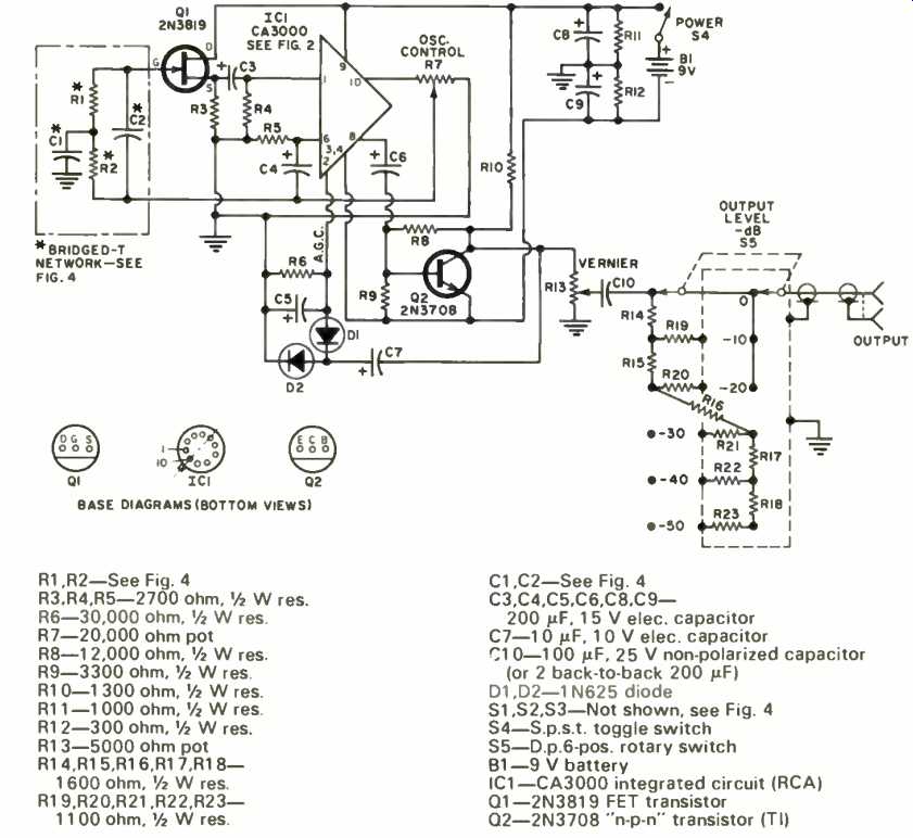
Fig. 1. Complete schematic diagram and parts listing for the solid-state
generator.
HAVE you ever wished you could set your audio generator for to a particular frequency and know you could rapidly return to the same frequency later or that you could rapidly and accurately select a precise frequency anywhere within the audio range? This IC audio generator permits this to be done using three operating controls providing two switch-selected digits and multiplier. The generator provides an output level constant for all frequencies.
As can be seen from Fig. 1, the audio generator consists of an integrated-circuit amplifier with three feedback loops: (1) an adjustable broadband positive-feedback loop; (2) a frequency-selective (bridged-"T ") negative-feedback loop; and (3) an automatic gain control (a.g.c.) loop.
The integrated circuit, shown in Fig. 2, consists of a single-stage differential amplifier (Q2 and Q4) with input emitter-followers and a constant-current sink (Q3) in the emitter-coupled leg.
The gain of the dual-input, dual-output circuit is approximately 30 dB at frequencies up to 1 MHz.
One output from the integrated circuit is applied through capacitor G2 as broadband positive feedback. This output signal is also applied as negative feedback through the bridged-"T" frequency-determining network. As Fig. 3 indicates, the bridged-"T" network has very high impedance at the resonant frequency, falling off rapidly on either side. Consequently, the entire circuit oscillates only at that frequency at which the positive feedback exceeds the negative feedback.
The frequency-determining accuracy of the bridged-"T" network is strongly dependent on loading. A source-follower field-effect transistor (FET) stage, corresponding almost exactly to a pentode cathode-follower, raises the IC amplifier's input impedance to several megohms. Probably even higher frequency-determining accuracy could be obtained using an insulated-gate FET. The other IC output, which has a signal level of about 0.1 V p-p, is connected to a conventional common-emitter amplifier stage, Q2 in Fig. 1. Part of the output of this stage is rectified, filtered, and applied to the a.g.c. terminal of the IC amplifier. This a.g.c. compensates for temperature, power-supply variations, and frequency-determining network losses to provide an output which is pure sinusoidal and constant in amplitude for all frequency settings, within about 1 dB. (For those readers who, like the author, enjoy redesigning before building, it should be emphasized that the a.g.c. is not unnecessary. Without it, the unit varies between not oscillating at all and overloading. Results are quite poor.) This output from Q2 is also applied through the output Vernier control and the Output-Level attenuator which permit varying the output level continuously or else in 10dB steps. With the Vernier control set at a maximum, the Output-Level steps correspond to approximately 3 mV to 1 V in six steps.
Construction
Construction of the audio generator is not critical. However, careful work is required, especially when wiring the frequency-determining network (Fig. 4). Obviously, no generator is more accurate than the frequency determining components in it.
The generator was constructed in a 4" X 5" X 6" metal box. The three lowest level stages of the attenuator were constructed inside a copper shield, as shown in Fig. 1, to avoid contamination of the very low level output signal.
All parts except those attached directly to the switches were mounted on a Vectorboard. Short leads should be used throughout; in particular, leads between the frequency-determining network and the IC input should be direct and dressed away from all other signal leads. The two transistors used are economy-type plastic encapsulated units and are readily available. Total list price for the two transistors and the IC was about $6.00. The diodes can be any general-purpose silicon types. The battery should be the largest-capacity 9-volt type convenient, or an external power supply can be used.
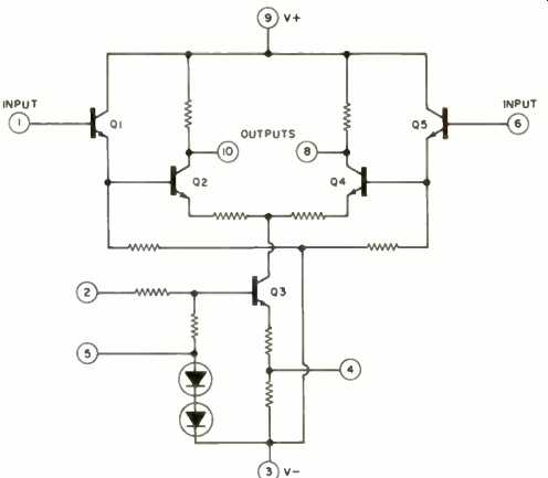
Fig. 2. Internal circuit and connection for the CA3000 IC.

Fig. 3. Circuit oscillates at the single frequency at which positive
feedback just slightly exceeds negative feedback.
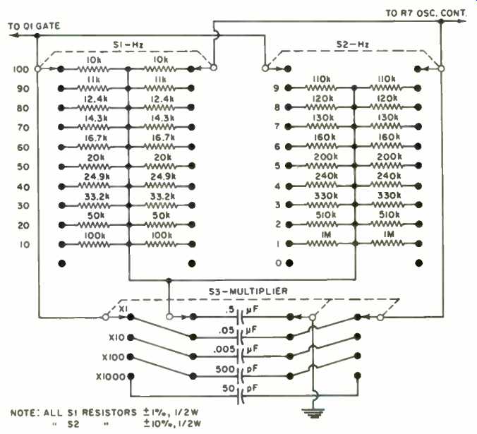
Fig. 4. Component values and switching for bridged-"T" network.
Alignment and Troubleshooting
To align the unit, adjust the oscillator control for an a.g.c. voltage of 0.7 to 0.8 V d.c. At this setting, the output should be a clean sine wave at all frequency settings. If distortion is apparent at some settings, set the control for a lower a.g.c. voltage; if oscillation does not occur at some settings, the setting is too low. Once set, there should be no reason to change the setting. If readjustment seems indicated at some later time, check the battery voltage first.
(Note: When making any internal or external adjustments, except output-level adjustment, allow 5 to 10 seconds for the output to stabilize.) Since 1-percent precision capacitors are not commonly available, it may be desirable to pad the capacitors on the frequency-multiplier switch to calibrate the audio generator against a known frequency.
An oscillator circuit can be very difficult to troubleshoot, since every part of the circuit interacts with every other.
Some things to watch for are: Failure to oscillate at some frequency settings: Look for defects in the frequency-determining networks or excessive loading caused by a defective FET. Inaccuracies at higher frequencies: Look for capacitive coupling between the positive- and negative-feedback circuits.
Inaccuracies at the higher settings for each multiplier setting: Look for an excessive amount of network loading.
Inability to set oscillator control as required: First, check the battery. Then check the a.g.c. circuit. If both of these check out, a slight adjustment in the power-supply voltage divider may be in order.
======
======
(adapted from: Electronics World magazine; Jul. 1975)
================