By FRANK H. TOOKER
A typical solid-state regulated power-supply circuit is shown in Fig. 1A. A transformer's secondary voltage is rectified and applied across a filter capacitor, C. Zener diode, D, fed through a current-limiting resistor, R, regulate, the output potential.
For best regulation, the voltage drop across R should be as large as possible, which means that the voltage rating of C must be quite high--perhaps twice the value of the regulated output voltage.
The requirement for low ripple in the output demands a value of several thousand microfarads for C. This combined need for high capacitance and high voltage means large size and high cost. Furthermore, the high capacitance puts a high surge current demand on the rectifier and the transformer, every time the power supply is turned on.
The author prefers to use the circuits shown in Figs. 1B and 1C. Here, the current-limiting resistor, R, has been located in the a.c. side of the circuit rather than in the d.c. side. As a result of this simple change, both size and cost of the filter capacitor are reduced. The capacitance value stays the same as before, but the voltage rating now needs to be no higher than the output voltage.
This can represent quite a saving, since it usually means dropping the voltage rating of the capacitor to one-half the rating required by the circuit in Fig. 1A. Relocating the resistor also allows it to limit the surge current required to charge the capacitor at each turn-on of the supply.
The circuit of Fig. 1B may use either a single resistor (as shown) or a pair of resistors--one in each side of the a.c. circuit--each having one-half the required total resistance and one-half the power rating. The value of R in Figs. 1B and 1C is determined by the required zener-diode current and the maximum and minimum current demands of the externally connected circuit. It need not have the same value in the a.c. location as may be required in the d.c. location.
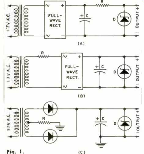
Fig. 1.
======
Portable Sound Systems for Performers -- Part 2 -- Amplifiers & Loudspeakers
======
(adapted from: Electronics World magazine; Jul. 1975)
================