By DAVID L. HEISERMAN
Optical-electronic scanning system accurately records type, owner, registration number for every freight car in a train moving at speeds up to 80 miles an hour.
HERE are about 1.8 million freight cars on the tracks in the United States and Canada. The paperwork involved in keeping tabs on all these cars has always created monumental problems. To complicate the situation even further, railroads share cars and facilities freely, but have different ideas on how to handle the necessary paperwork. It's little wonder, then, that losing track of a couple hundred freight cars for a day or two is a common occurrence.
With the help of the Association of American Railroads (AAR), the rail industry tried to cut down on paperwork and keep better track of its cars by installing sophisticated data-processing and communications centers.
During the 1960's, most of the routine paperwork involved in keeping track of cars began to diminish, and the flow of inter-company information improved considerably.
A few years' experience, however, showed there was still something wrong with the system. The AAR began working on the problem as early as 1959 and, by late 1967, provided the solution.
It seems that the weak link in the new railroad data-processing system was in the information input phase of the operation. The computers were handling available data as well as could be expected, but the input data was going into a modern system by means of an iron-horse-age technique-a clerk with a clipboard, pencil, and a check sheet noting cars on a passing train. Unless the train happens to be going by at less than about 20 miles an hour, it is difficult to verify or record registration numbers visually with any degree of accuracy. And if the input information is faulty, a computer can cause more problems than it solves.
The automatic-car-identification (ACI) system proposed by the AAR could accurately record the type, owner, and registration number for every freight car in a train moving between zero and 80 miles an hour. In 1967, the AAR accepted a Sylvania version of the ACI system. Marketed under the tradename KarTrak, there are now more than 150 of these ACI systems in full operation in North America and many times more expected by 1975.
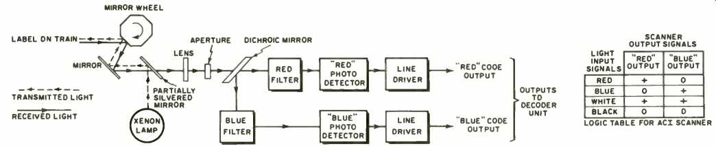
Fig. 1. Block diagram of Sylvania's ACI scanner. It is apparent that red and blue are the two basic colors used, with black indicating absence of color and white used to excite both channels. As each color is scanned, it produces a pulse of a specific duration. In the case where dual red or dual blue stripes are used, the electronically timed pulse width is equivalent to two shorter pulses. The system of conversion from color stripes into numbers is the Steits method (after Francis Steits, the designer). These color stripes are electronically converted first into pulses and, through the use of 2 separate channels and 4 flip-flops, are then converted into numbers in the conventional binary manner. Refer to the text for complete details.
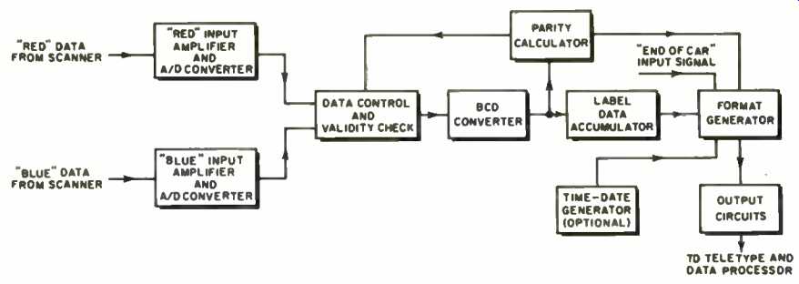
Fig. 2. The ACI decoder unit processes data from the scanner and prepares
it for transmission to distant Teletype printers and data-processing
units.
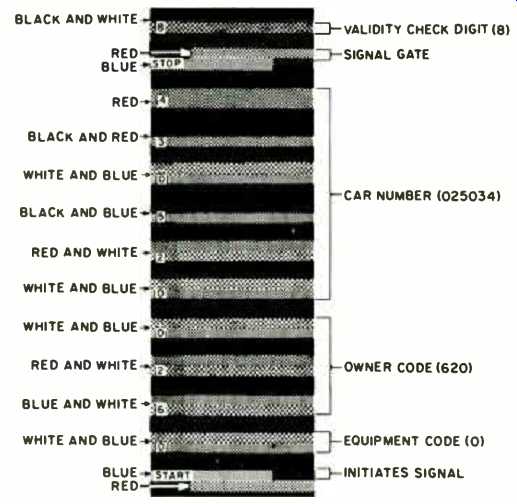
--------ACI labels are made of 3M's "Scotchlite" retro-reflective tapes.
The non-reflective black background provides a "no-signal" input to the scanner. The ACI system converts the color-coded labels into a conventional, easy-to-process Teletype print-out.
------ Sylvania's automatic-car-identification scanner shown being used to read a label on a "piggyback" car carrying a trailer.
How ACI Works
The KarTrak ACI system consists of three parts: (1) a set of retro-reflective color-coded labels which are applied to each side of a freight car, (2) a trackside optical-electronic scanner that reads the labels as the train moves past, and (3) a data decoder and transmission unit that digitizes the scanner's output and transmits the data to far-away Teletype printers and data-processing units.
The labels are made up of 13 color-coded strips of red, blue, and white Scotchlite tape. The strips, arranged in a ladder-like fashion, lie within a 10 x 22 1/2-inch area of non-reflective black paint. The information coded into a label includes the type of car, its owner, and its registration number.
An approaching train activates a switch that turns on the power supplies and ignites the xenon lamp inside the scanner. A set of rapidly rotating mirrors make the scanner send out a beam of bright light that scans the side of the train in an upward direction. When the beam scans across one of the labels, a string of color-coded dashes of light reflect into the scanner.
The incoming pulses of light first pass through a series of mirrors, a lens, and an aperture. The next element they encounter is a dichroic mirror-a special optical device that reflects light of one color and transmits light of another color. In the KarTrak scanner, the dichroic mirror directs the red and blue pulses of incoming light to separate sets of colored filters and photo detectors.
The detectors, in turn, generate a pulse of electrical energy when they're activated.
A pulse of blue light reflected into the scanner, for example, activates only the "blue" photo detector. A pulse of red light, on the other hand, activates only the "red" detector. Since white light is actually a mixture of all colors, the dichroic mirror separates both red and blue light from incoming pulses of white light. A pulse of white light, then, activates both detectors. To complete the logic scheme, the black portions of a label produce no reflected light, and neither photo detector generates an output signal. See Fig. 1 for a block diagram of the scanner.
After leaving the photo detectors, the label code is still intact, but in the form of electrical pulses rather than strips of color-coded tape. A pair of line drivers delivers the two sets of scanner signals to the decoder unit.
The input section of the decoder unit contains two sets of amplifiers and analog-to-digital converters that clean up the detector outputs and adjust their pulse heights and widths to meet a standard format. The data is then serially loaded into a logic circuit that performs a preliminary validity check on the information. A red-light reflector on the side of a boxcar, for example, could activate the system unintentionally. This single pulse of red light, however, cannot pass the first validity check, so the logic circuit would scrap the entry. Data that passes the first validity check goes through a binary coded decimal (BCD) circuit that converts binary into standard decimal code. This completes translation of the labels into decimals. (See Fig. 2.) The decimal numbers accumulate in a storage register until all the information for one label is in. At the same time, data goes to a circuit that runs a complete parity check on the information. If the circuit calculates a "bad" parity, a logic circuit instructs the system to receive data from another scan over the same label. The system, in fact, continues to accept a label's code, check, and recheck the data until either the parity circuit finds "good" parity or the label moves out of the scanner's range.
At the user's option, the label data can be stored and retrieved at a later time, or sent through leased lines to a distant Teletype and computer center as soon as the car passes over a magnetic "end of car" sensor mounted on the tracks. In either case, the data leaves the decoder unit via a format generator that establishes the formal layout of information for the Teletype printer.
Optional Features
Among the most common optical ACI features are a digital time-date generator, multiple scanner units, and piggyback readers. There are other optional features available from Sylvania, but they are mostly concerned with formatting and data-transmission techniques.
Railroads must use at least two scanners where there is the possibility of two trains passing the same place at the same time. Sylvania engineers designed a duplexer circuit that lets a single decoder unit accept simultaneous inputs from more than one scanner.
A popular trend in modern railroading involves shipping freight on flatcars loaded with "piggyback" truck trailers or special shipping containers. The ACI piggyback option allows the user to place a label on the flatcar and on each of the vans or containers riding "piggyback" on it. The scanner then reads all the labels and the decoder prepares a Teletype and computer format that shows information about the flatcar and every piece of equipment on it that carries an ACI label.
======
======
(adapted from: Electronics World magazine; Jul. 1975)
================