By GEOFFREY F. WALKER /Hewlett-Packard Co.
SCR supplies are designed for applications requiring large amounts of fixed or slowly varying, moderately well-regulated and moderately ripple-free d.c. power.
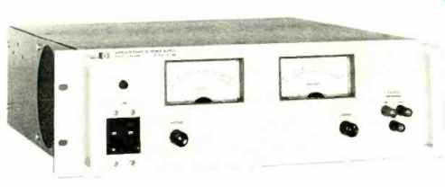
-------- Typical rack-mounted SCR type power supply. The output is
0 to 600 volts and 0 to 1.5 amps.
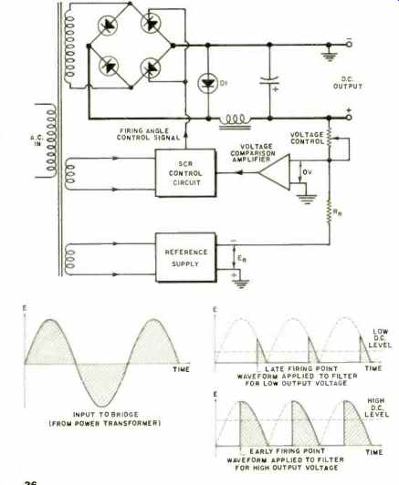
Fig.1. A secondary-regulated, constant-voltage SCR power-supply in which
the SCR's are included in two arms of the bridge rectifier.
THE SCR power supply was developed to supply loads requiring substantial amounts of fixed or slowly varying d.c. power with moderate regulation and ripple. Covering (and dominating) the d.c. output power range between 1 kW and 30 kW, SCR power supplies use silicon controlled rectifiers (thyristors) as their regulating element. SCR's, the semiconductor equivalent of thyratrons, are rectifiers which remain in a non-conductive state, even when forward voltage is provided from anode to cathode, until a positive trigger pulse is applied to a third terminal (the gate). Then the SCR "fires," conducting current with a very low effective resistance; it remains in conduction after the trigger pulse has been removed until the forward anode voltage is removed or reversed.
Regulator Operation
There are two basic SCR power-supply circuit configurations: primary regulation and secondary regulation. Fig.1 shows a secondary-regulated, constant-voltage SCR power supply in which the SCR's are included in two arms of the bridge rectifier. By controlling the firing time of the SCR's during each half cycle of input line frequency, the duration of conduction of the bridge rectifier is varied and the d.c. output is controlled in accordance with the setting of the output voltage control.
Diode D1 across the bridge output is a "recirculating" or "freewheeling" diode. It discharges the energy stored in the filter choke at the moment the bridge stops conducting by providing an alternate path for the current flowing in the choke. If the diode were not present, the sudden current change in the inductor would produce a large voltage spike in the output.
The voltage-control circuitry shown in Fig. 1 is common to almost all regulated power supplies, irrespective of the regulating method employed. The heart of the circuit is a voltage-comparison amplifier that continuously compares the supply output voltage with the drop across the front-panel voltage control. If these two voltages are not equal, the comparison amplifier produces an error signal that, when applied to the SCR control circuit, adjusts the SCR firing time (and thus changes the current through the load) until the output voltage equals the voltage across the voltage control.
Fig. 2 is a diagram of a primary-regulated, constant-voltage/constant-current SCR power supply. Here the SCR's are connected in shunt opposition and placed in series with the primary of the power transformer.
It is apparent that in this arrangement the SCR's play no role in rectification; instead, the SCR's control the average a.c. level applied to the power transformer. Notice that the transformer primary is not required to sustain the full power-line voltage; with a 115-V, single-phase a.c. input, the highest voltage typically measured across the primary is equivalent to an 80-V r.m.s.
sine wave. This results in a substantial saving in size and weight of the power transformer and consequently of the entire power supply.
The constant-current circuitry shown in Fig. 2 operates in much the same manner as the constant-voltage circuitry; a comparison amplifier continuously compares the drop across the front-panel current control with the IR drop developed by the load current flowing through the current sampling resistor. If the two voltages are momentarily unequal, the comparison amplifier produces an error signal that, when applied to the SCR control circuit, varies the SCR firing time until the two voltages are again equal. Although constant-current circuitry is shown only in the primary-regulated supply, it can be (and usually is) used in all types of SCR supplies.
Fig. 3 illustrates another type of power supply utilizing SCR's: the series-regulated /SCR-pre-regulated supply. This circuit uses a series regulator to reduce ripple, absorb transients, and handle rapid, low-magnitude regulation of the output; and an SCR pre-regulator to handle large, relatively slow regulation demands. The preregulator also minimizes power dissipation in the series regulator by maintaining the voltage drop across it at a low and constant level. Note that in Fig. 3 the primary SCR's have been replaced by a triac (a bi-directional device that can conduct current in either direction, and fires whenever it receives a gating pulse, irrespective of the polarity of the input a.c. applied to it); the use of this device is very common in modern SCR pre-regulated supplies.
Performance Specifications
After output voltage and current ratings, the main criteria by which a power supply is selected for a given application are its performance specifications: line and load regulation, ripple and noise, stability, temperature coefficient, and transient response. Specifications for a typical constant-voltage SCR power supply are as follows: Line and load regulation: 0.05% for a load current change equal to the rating of the supply.
Ripple and noise: 0.5% r.m.s. for a supply without a "ripple reducer" circuit, 0.05% r.m.s. for a supply with a "ripple reducer" circuit, and 3.0% p-p (d.c.-20 MHz) for both supplies.
Stability: 0.2% under constant load, line, and temperature conditions.
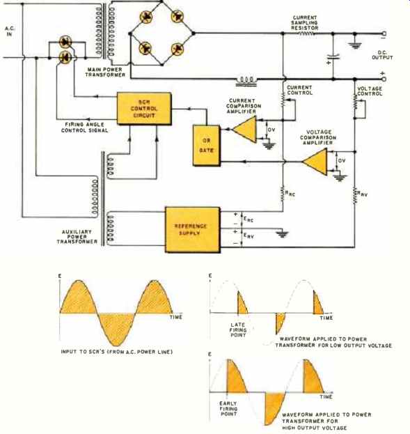
Fig.2. Circuit of a primary-regulated, constant-voltage /constant-current
SCR power supply. SCR's are not used for rectification but control a.c.
applied to power transformer.
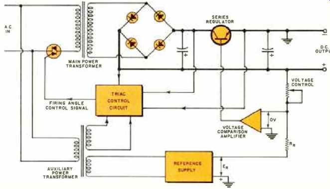
Fig.3. Another type of power supply using SCR's- series-regulated /SCR
pre-regulated.
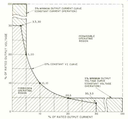
Fig. 4. All SCR supplies have output restrictions. Unfortunately, some
manufacturers erroneously specify or completely neglect to specify
forbidden output operating regions.
Temperature coefficient: 0.05% per degree centigrade change in ambient following a 30-minute warm-up period.
Transient response: 100 ms for recovery to within 0.5 V after a half-to-full or full-to-half load current change.
These are typical values only; manufacturer's specifications for different supplies vary over a moderately wide range. For example, SCR supply load and line regulation is nearly always in the range of 0.01 % to 0.5 %. (Actually, regulation is usually specified as a percentage term plus a fixed term, because the percentage term alone does not accurately describe the regulation at low outputs. The combined expression can, of course, be converted to a single percentage term at any given output voltage.) It is important to realize that the "all in the same ball park" principle applies to power-supply specifications--if load regulation for a given supply is 0.05%, a stability specification of 0.0001% for the same supply is pointless. Thus, while it is possible to greatly improve some of the specifications of an SCR supply (such as stability and temperature coefficient), the nature of the basic design limits the overall performance. For example, the transient response is limited because regulation corrections can be made only once every half cycle of the a.c. input; this means that if there is a sudden load change immediately after the SCR has fired, no correction can be made (for a 60-Hz, single-phase supply) until at least 8.3 ms later. Another limiting factor also affecting the response to load transients is the amplifier bandwidth--it must be significantly less than the a.c. line frequency to avoid oscillation (gain crossover, the frequency at which the amplifier gain is unity, is typically 10-15 Hz in SCR supplies). Ripple and noise is another specification that is limited by the basic nature of the SCR power-supply design. High-frequency ripple (spikes) is a natural by-product of the switching technique employed in an SCR supply; although considerable effort is made to counteract this problem in modern power supplies, the magnitude of the remaining peak-to-peak ripple is sufficient to bar the use of SCR supplies in many applications. The r.m.s. ripple, however, is a different story. It is quite possible to reduce r.m.s. ripple to very low levels either through the use of massive LC filters, or through "ripple reducer" circuits. In operation, the latter senses ripple at the output of the supply, amplifies it, and applies it to a control circuit. The control circuit in turn applies an auxiliary a.c. potential to the supply output; this a.c. potential is 180° out-of-phase with the normal ripple voltage, effectively filling in the valleys of the output voltage. However, in applications where moderate load regulation and moderate peak-to-peak ripple is acceptable, very low r.m.s. ripple is usually not required (this is the "all in the same ball park" principle again).
Other Characteristics
Other notable characteristics of SCR supplies include efficiency, reliability, size (watts per cubic inch), value (cost per watt), and functional features.
The switching technique used in SCR supplies results in an efficiency of 80 to 90% at the supply's maximum output rating; as the supply is turned down, the efficiency remains above 50 to 60%. By comparison, series-regulated supplies rarely reach 60% efficiency even at full output, and at lower outputs (where the series regulator must dissipate the unused power), their efficiency drops to 10% or less. Compared with other types of supplies in the same power range (ferroresonant, mag amp, and Variac-preregulated), SCR supplies are still more efficient, although not by as great a margin.
In general, there is an inverse relationship between the number of electronic components in a power supply and its reliability (as the former rises, the latter falls). SCR supplies use more components than ferroresonant or mag amp supplies and fewer components than series-regulated supplies; thus the reliability of SCR supplies falls somewhere between the two.
Present SCR supplies exhibit an increasing power /volume relationship--as the power output goes up, the watts/ cubic inch (W /in^3) goes up. Typically, a 1 kW-5 kW SCR supply may offer 0.55 to 0.70 W /in^3, while a 10-kW supply may offer between 0.9 and 1.5 W /in^3. (This is significantly different from the typical 0.08-0.15 W /in^3 figure for series-regulated supplies.) The relationship between power output and price is less distinct; SCR-type power supplies in the 1-10 kW range generally cost between $0.25 and $0.65 per watt.
Modern SCR supplies are very similar to other types of supplies in their functional (operating) features; most supplies include remote-programming and remote-sensing capability, CV /CC operation, front-panel meters and output controls, parallel and series operation, optional over-voltage crowbar, and adjustable loop response. This last feature is particularly necessary due to the unusually wide range of load impedances that may be connected to an SCR supply (storage batteries present from 1 to 10 farads of capacitive load, while cryogenic magnets present from 1 to 10 henrys of inductive load).
Distinctive Operating Characteristics
SCR power supplies exhibit a unique set of "operating peculiarities," again due to the nature of the basic design.
These include a minimum output restriction, a sensitivity to line transients and line-to-line voltage imbalance (in three phase supplies), and large short-circuit energy surges.
All SCR supplies have a minimum output restriction that is determined by the characteristics of the SCR and the particular firing circuit used. At very low outputs, the SCR may skip one or more half-cycles of the a.c. input, degrading the regulation, transient response, stability, and linear programming characteristic. As a result, some manufacturers specify a forbidden-output operating region, such as that shown in Fig. 4. For the particular case shown, the supply will not meet published performance specifications as a constant-voltage source at less than 5% of its rated output voltage, or as a constant-current source at less than 5% of its rated output current. In addition, when the supply is operated at low voltage and low current levels, the output power is further restricted to at least 10% of its maximum value.
Line-transient sensitivity, another peculiarity, occurs because an SCR supply has no active element in its power mesh (the SCR is either "on" or "off"-it has no linear mode of operation as does a series transistor). When the SCR is on, any momentary change in the a.c. line voltage is passed through to the output.
In higher-power SCR supplies where three-phase input is used (with three SCR's), a voltage imbalance of only a few percent between input phases can cause a low d.c. level to appear across the power transformer primary; this d.c. voltage applied to the very low d.c. primary resistance causes a large d.c. primary current to flow, tripping the circuit breaker or blowing the fuses.
However, at least one manufacturer's SCR supplies incorporate a circuit that senses the line-voltage imbalance (within a certain limit) and adjusts the firing time of one of the three SCR's accordingly, thus eliminating the problem completely.
Finally, the unusually large output filter capacitor used on most SCR supplies causes a large initial current surge when the output terminals are short-circuited, even if the supply is in constant-current operation, because the capacitor is nearly always outside the constant-current feedback loop.
Applications
As previously mentioned, SCR supplies were developed for applications requiring large amounts of fixed or slowly varying, moderately well-regulated, moderately ripple-free d.c. power. Presented below are ten of the most typical applications with such requirements: Life testing and aging large quantities of such components as power transistors, rectifier diodes, zener diodes, incandescent lamps, circuit breakers, and d.c. contactors.
Supplying power to computer mainframe and memory systems (8 volts at 1000 amperes is a typical supply rating used here). Magnet supplies for cyclotron, magnetohydrodynamic, and cryogenic (superconducting) magnet applications.
Battery charging and discharging.
SCR supplies with constant-voltage / constant-current automatic crossover are frequently used to charge and discharge large storage batteries (such as those used in electric warehouse trucks) at constant current. In charging applications, when the maximum charge voltage is reached, the supply automatically switches to constant-voltage operation and supplies a trickle charge sufficient to maintain full charge. Taper charging is accomplished with the same supply by inserting a small resistance between the supply and the battery; this causes the normally flat constant-voltage output characteristic to take on a finite slope.
Supplying d.c. filament current for superpower tubes, such as those used in linear accelerators (3.5 V, 3500 A is a typical supply rating used in this application).
Precision tungsten /inert-gas arc welding for cleanliness and hermetic seals in such components as crystal-case relays and aneroid bellows; precision aluminum welding during aircraft assembly. SCR supplies are also used to test welds such as those between storage-battery plates and terminals; in this application, a 1000-A current is put through the weld, and the resulting millivolt drop is measured across the weld using the four-terminal Kelvin method. The same Kelvin method is also used when testing high-current meter shunts.
Precision electroplating, usually with precious metals. SCR supplies are also used in chrome-plating large quantities of machine parts, and in other high-current electrochemical processes.
Testing high-current electrical systems such as large telephone switch-boards and luxury automobile electrical systems. Also in this same area, SCR supplies are used in processing (forming) electrolytic capacitors.
Controlling and operating d.c. motors; replacing motor-generator sets in older industrial operations.
Powering air-conditioning systems using the Peltier effect (the production or absorption of heat at the junction of two metals when a current is passed through the junction). What's Ahead?
What's ahead in SCR power supplies? Perhaps the largest factor on the near horizon is the gate-controlled switch (GCS). These are SCR's that can be turned off as well as on by the application of a pulse; their future availability in high-power ratings may cause major changes in the design philosophy of SCR supplies.
First, SCR regulators will no longer be limited to operation at the line frequency; with the ability to turn off the SCR when desired, the regulator can be made to operate at a higher frequency. This will result in an even smaller supply due to smaller transformers and filters. Second, the higher operating frequency will result in improved transient response and programming speed. Third, the ability to turn off the SCR at any time during the a.c. input cycle will provide greater supply reliability. In present supplies, a fault occurring immediately after an SCR fires may cause the peak current in the SCR to exceed the safe maximum because the device cannot be turned off until the end of the a.c. half cycle. With GCS's, a fast-acting electronic circuit (rather than the presently used electromechanical devices) could turn off the gate-controlled switch early enough to avoid any possibility of damage.
Finally, there will undoubtedly be a continuing improvement in value (cost per watt) and output range of SCR supplies as prices of semiconductors continue to fall and maximum device voltage ratings continue to rise.