(source: Electronics World, Dec. 1971)
By L. GEORGE LAWRENCE
One of the least expensive ways of getting an electronics package up into the outer reaches of the atmosphere. Description of some of the more unusual types, including advantages and limitations.
LARGE balloons are convenient vehicles for putting a sizable package of electronic instruments at the outer reaches of the atmosphere, typically at an altitude of 150,000 feet or more.
Sooner or later, a modern "aerostat" (the scientific name for these helium filled plastic bubbles) might well float across your professional career and invite your understanding and use. This article profiles some of the more interesting types of instrumentation balloons--their virtues and limitations.
From Montgolfier to Polyethylene A balloon may be described as an aircraft lacking a propulsive system. J. M. and J. E. Montgolfier of France are credited with its invention in 1783.
Also in 1783, the Robert brothers and J. A. C. Charles ascended and traveled about 27 miles in a hydrogen-filled balloon. Numerous other flights followed both here and abroad, but it was in the United States that the balloon's capabilities as instrumentation carriers were recognized and used.
Thaddeus Lowe, perhaps the best known of the early pioneers, was the first to use a balloon-borne telegraphic transmitter to direct gunfire. Another first was the use of balloon-flown cameras to take pictures of military ground emplacements. Before Richmond, during May, 1862, the entire battle zone was mapped in 64 overlapping photographs taken from a height of 1000 feet. Later, following the Wright Brothers' invention of powered aircraft, balloons remained popular for weather observations and as research vehicles for daring men like August Piccard (1884-1962) who ascended to a height of 55,500 feet in 1932.
Today, scientific ballooning has come almost full circle. Modern balloons are, in essence, electronic-payload carriers occupying a position between high-altitude airplanes and space satellites. Balloon envelopes of 65 million cubic feet interior volume have been built and flown, and larger ones are on the way. The large instrumentation balloon is one of the least expensive means for carrying things to altitudes above 99.8% of the Earth's atmosphere (2 millibars of pressure), where they can remain for many hours and transmit a large amount of geo-physical data. Here, an instrumentation package might contain infrared and x-ray telescopes, cosmic-ray counters, pressure and temperature sensors, and particle samplers.
All this might sound very elementary and traditional. But such feats gain stature when we realize that the effective carrier, the balloon itself, is little more than a carefully shaped and sealed piece of polyethylene less than 75/1000th of an inch thick--a fourth the diameter of a human hair.
Characteristics
Scientists use four types of balloons for meteorological and other research.
The extensible balloon outranks any other. This vessel is designed for light loads-like a radiosonde-which it will carry to its burst altitude of from 100,000 to about 130,000 feet.
Next comes the zero-pressure balloon, a vented design, which is the workhorse for scientific research and carries the heaviest payloads to the very highest altitudes.
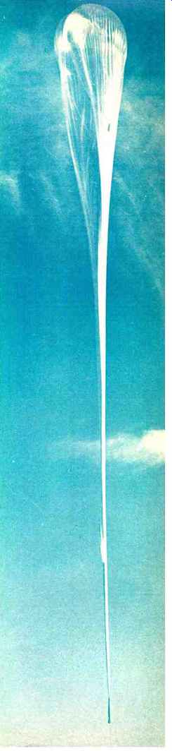
----A rising instrumentation balloon just after launching. At its
operating altitude over 100,000 ft, balloon will attain the shape
of a sphere and be over 200 ft in diameter.
A third type is the super-pressure balloon, a closed vessel made of strong materials whose volume remains constant. This aerostat floats at a constant-density height and, theoretically at least, needs no ballast to maintain effective altitude when it cools down at sunset. By contrast, the vented zero-pressure balloon must dispose of ballast under the same flight conditions--typically about 5% to 7% of its gross weight. The jettisoning of ballast limits the balloon's useful service life to about one week.
A fourth type is called the open-appendix hot-air balloon.
Today, aside from improvements in hull materials and sources of heat (propane burners), it is of the same classic design as the one which carried the first man above ground in 1783. As an expendable design, it can be used in various applications where no great low oxygen altitudes are involved. However, it is the zero-pressure balloon which is of particular interest to electronics men.
Prior to the advent of helium as the lifting medium, highly dangerous hydrogen gas was in general use. In an early generator, steam was sprayed over red-hot iron filings. The decomposing water released hydrogen as the oxygen combined with the iron. The hydrogen was then carried through a pipe into the water chamber and from there into the tethered balloon.
Pre-inflation always posed a problem. But, hot-air types can be pre-inflated by large blowers to reduce danger to the hull from the open flame of the heat source.
Helium has a lifting power of 66 lb for every 1000 cubic feet. Thus, a balloon's ground-level charge of, say 10,000 cubic feet, will generate a lift of 660 lb. The excess lift over the balloon's material weight is termed the "free lift" and provides an ascent rate of about 1000 feet per minute.
One of the photos shows charging operations. The polyethylene balloon, a zero-pressure type, receives the helium through a plastic hose on the top. The vessel is restrained by running the top section of the folded part through a launch spool attached to the helium truck's front end.
As inflation progresses, the helium truck inches forward--toward the instrumentation package. The latter rests on a launch truck at some distance from the balloon's big bubble. In this way, more and more of the balloon is allowed to emerge safely from the launch spool and reach the free air above it.
The launch spool is equipped with explosive bolts that hold it closed. Also, a load cell or similar weighing device is attached to the spool to measure effective lift against the amount of helium drawn from the truck's storage tanks. A small pilot balloon, clearly visible in the photo, will be released just before launch to indicate wind direction at the launch site.
For the actual launch, the explosive bolts are fired, the launch spool opens, and the balloon rises-but it's not yet free. To prevent damage to the payload by being dragged over the ground, the driver of the launch truck moves his vehicle to a point where, in his estimation, the swinging balloon will arrive just as its envelope has stretched to full length. Then, if all goes well, the instrumentation package gently lifts off its cradle on the launch truck and another experiment is on its way.
Balloon Failures
Although we are accustomed to regard balloon lift in terms of Archimedes' principle--buoyancy being equal to weight of fluid displaced-it gives us little insight into the physical processes involving the lift provided by a balloon.
Great stresses are brought to bear by the lift of the gas, with other stresses exerted on the envelope by the balloon's weight and the scientific payload, gondola, or other attachments. If these stresses are not carefully balanced out, the balloon tends to fail.
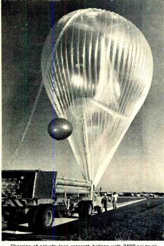
---- Charging of polyethylene research balloon with 2400-psi truck
tanks. Helium is fed though plastic hose on top. Launch spool, mounted
in front of trick, restrains balloon during charging.
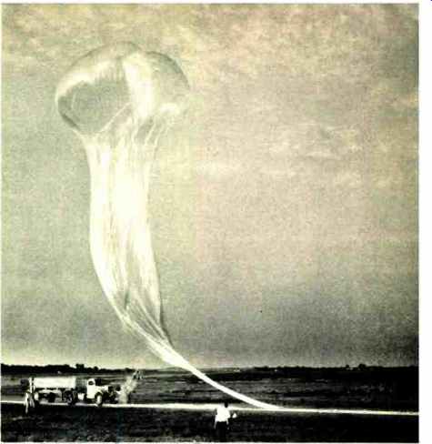
--- The instrumentation balloon has just been launched, after launch
spool has been released by explosive bolt. The electronics payload is
off the photograph at the extreme right.
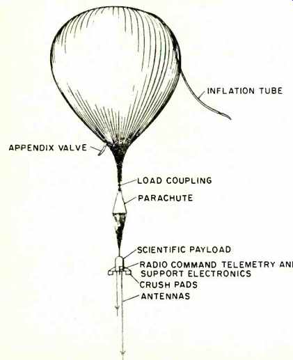
Fig. 1. Components of a typical balloon flight train.
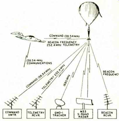
Fig. 2. Balloon instrumentation systems. Not only is the payload electronic
but electronics is also used for the ground based tracking and telemetry
which keeps tabs on the flight.
It was largely due to the work of Dr. Ralph Upson, then at the University of Minnesota, that progress has been made in analyzing the effects of shape on possible stress concentrations. Typically, a high-altitude balloon faces its greatest danger not during launch, but during ascent. The lift force of the helium must be absorbed in a relatively small area of the upper part of the polyethylene film, yet over-all balloon design is based upon fully inflated conditions.
From common launch to free float, the helium expands as much as 500 times. At from 30,000 to 60,000 feet, the altitudes of typical failures, the balloon is only 5% to 15% inflated. The polyethylene envelope tends to change, as the balloon ascends through the various layers of the atmosphere, from a pliable amorphous plastic to a brittle crystal-line structure susceptible to rupture.
However, various means of reinforcement are available.
J. A. Winker, president of Raven Industries and one of America's major balloon makers, has investigated techniques of local envelope reinforcement such as the "Vista Dome." The research balloon has a capped top whose radius roughly equals that of the initial-inflation bubble. During inflation and early flight, the polyethylene film "hangs" from this small top. Later, at service altitude and fully inflated to a spectacular and almost spherical shape, the vessel takes on the appearance of an ordinary zero-pressure balloon-except for the small dome on top which resembles the observation deck of the "Vista Dome" railroad car.
The Winzen Research Corporation, another major balloon maker, has introduced new balloon materials which have passed the cold-brittleness tests at -80°C and -84°C. Thus, the temperature gradients of the atmosphere in general and the balloon-killing capacity of the tropopause in particular, have lost much of their costly sting.
Electronics for Tracking
Fig. 1 shows a typical flight train, while Fig. 2 depicts representative instrumentation systems. Principal components include the balloon, a load-coupling arrangement, the recovery parachute and the scientific payload connected to it, support equipment, and crush pads. Some vessels frequently are provided with a rip panel to permit quick gas release upon flight termination.
The determination of balloon trajectories, including overall balloon performance at the service altitude, is of great importance in scientific ballooning. First, if we look at the balloon itself, we find it to be a rather efficient (if undesirably so) thermal machine. Solar hearing causes the balloon to rise above a given reference float level, while cooling at sunset causes it to drop below the level. Some control can be exercised by allowing excess lifting gas to escape through an appendix duct or use so-called "dribbling" of ballast to make the vessel level off when over-all system density equals the density of the ambient atmosphere.
Radar can track a balloon within a radius of 50 miles.
Using S-band equipment, tracking uses only the natural reflectance of the balloon because balloon-carried radar transponders are not generally employed. The balloon's natural reflectance is increased by the use of a passive corner reflector target-basically a shaped sheet of metal-that has been carried aloft. Signal reflectance may also be improved by placing metalized film on the load tapes or seams.
As for telemetry, the FM/FM type is the most straightforward approach and has found wide acceptance in many other areas of space research. Data transmitted to ground stations is generally in the form of a varying d.c. voltage, usually ranging between 0 to 5 volts. These analog voltages, provided by transducing systems in the scientific payloads, normally frequency-modulate a voltage-controlled oscillator (v.c.o.) or, if a number of data sources are involved, sequencing is accomplished by fairly traditional commutators and final transmission systems. Frequencies of the various v.c.o.'s conform to specs established by the Inter-Range Instrumentation Group (IRIC). Ground range and slant range to the balloon can be calculated by trigonometric methods if the altitude is known.
Here the RAWIN set AN /GMD-1, a portable radio-direction finder which was designed primarily for automatic tracking of balloon-carried radiosonde transmitters, is put to use. The radiosondes operate at 1.68 GHz and transmit meteorological data in the form of amplitude or frequency modulation. On the ground. the AN /GMD-1 receiver uses a highly directional parabolic antenna, employing a spinning dipole and servo system for direction finding. Elevation and azimuth angles are measured from the antenna to the balloon with an accuracy of about ±0.05 °. Altogether, balloon-type electronics are not overly complex and tend to follow design principles found in traditional industrial telemetering equipment. As many as twelve or more tones may be available for command functions and/or special coding may be used to ensure privacy.