(source: Electronics World, Dec. 1971)
By RICHARD M CARTOSCELLI
The use of a unijunction transistor with a v.t.v.m. or scope permits accurate visualization of the circuit time constant.
OFTEN it is very difficult to learn the correlation between RC time constants and sawtooth waveforms. The advent of the unijunction transistor (UJT) has changed this entirely. The UJT will permit visualization of an extremely slow time constant with a v.t.v.m. (or solid-state v.o.m.), or a very rapid one with the oscilloscope.
A conventional circuit which has been used as a sawtooth wave generator is shown in Fig. 1A. by making either R or C larger or smaller, the charge time of the capacitor can be increased or decreased, respectively. What results is a rapid or slow blinking interval of the NE-2 neon lamp. The operation of the circuit is quite simple. The capacitor charges exponentionally until the firing voltage of the NE-2 is reached. Once the NE-2 has come on, it appears as a short circuit across the capacitor, thus discharging it instantaneously. The charging again repeats itself. Either a scope or v.t.v.m. can be placed across the capacitor to monitor the exponential voltage rise or sawtooth waveform.
The main drawback to the circuit of Fig. 1A is the high d.c. voltage required. The NE-2 has a firing potential of nearly 90 volts d.c. Additionally, the circuit does not lend itself to many experimental uses. On the other hand, the UJT circuit to be described and depicted in Fig. 1B permits several sophisticated techniques which can be integrated as a part of mathematical time-constant computations.
The operation of the circuit in Fig. 1B is as follows: Capacitor C charges exponentially through resistor R until the peak firing potential of the UJT is reached. At this point the base-1 resistance of the UJT approaches zero and C discharges nearly instantaneously through the UJT and RBI. Once C has discharged, the UJT's peak firing potential is no longer present and the UJT's base-1 resistance returns to its normal value. Thus what exists across capacitor C is an exponential sawtooth waveform. The values of C and R in Fig. 1B permit either a "slow sawtooth," capable of being observed with a v.t.v.m., or a high-frequency sawtooth which can be monitored with an oscilloscope.
To initially orient readers to the exponential properties of charging time, a "slow sawtooth" is used. Values of R and C in the UJT circuit are 270 k ohms and 20 F. Monitoring the voltage-rise across C with a v.t.v.m. reveals in initial fast movement of the meter's needle followed by a constantly reducing movement speed. This continues until the UJT's VP is reached, whereupon the meter's needle drops instantaneously toward zero. However, the capacitor discharge time is so rapid that the initial part of the next sawtooth appears again, and the mechanical travel time of the meter's needle is not capable of keeping pace. What virtually results is the meter's needle returning to approximately half-way between zero and the V, that was reached.
For a "fast sawtooth," values of C and R in the UJT circuit are reduced to 0.2 µF and 10k ohms, respectively. If a common 5 or 10 percent tolerance resistor is used, a careful measurement of its value should be made and recorded.
The same is true for the value of capacitor C. Once the circuit is set up into operation, a careful measurement of the time for one sawtooth is taken with an oscilloscope and recorded. Next the instantaneous voltage across C is calculated by the exponential formula: e= Emax(1-E_t' ) where: Emax= VBB, 10 volts; t= time of one sawtooth, seconds; R= actual value of R, ohms; and C= actual value of C, farads. A careful check should be made to determine if the VBB is set as closely as possible to 10.0 volts.
The actual intrinsic standoff ratio (eta) of the particular UJT being used must be determined. This can easily be done with the experimental circuit shown in Fig. 2 and the procedure that follows. The Cal button is depressed and R3 is adjusted to make the meter read full-scale. The Cal button is then released and the value of is read directly from the meter (1.0 full scale). The eta for the recommended 2N4891 UJT will be somewhere between 0.55 and 0.82.
The next calculation involves the peak firing potential of the UJT. The formula used is:
VP= VBB_eta + V_ F
where: VBB_eta =10.0 volts; eta = intrinsic standoff ratio of particular UJT being used; and VF= 0.56 volt at 25 °C. Following these calculations, the peak potential of the sawtooth wave is measured. The measurement is then compared with the two calculations. If the VBB has been accurately set to 10.0 volts and the UJT's eta was precisely measured, the calculation involved to find V, can stand as a point of reference. If both calculations and the measured value of the sawtooth check within 0.2 volt, the oscilloscope can be considered accurately calibrated on both horizontal and vertical inputs. In the event the measured the calculated values do not check, further calculations can be made to determine which scope axis is in need of calibration.
The time of one sawtooth is calculated by the following formula where t is solved for:
e = Emax(1-e^-t/RC)
where: e= VP, in volts (VP= VBB_eta + VF); Emax =10.0 volts; R= actual value of R, ohms; and C= actual value of C, farads. The time derived should agree with the measured time of one sawtooth. If the V, measured does not agree with the value calculated by Vp= VBB_eta + VF, the vertical calibration is not correct.
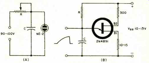
Fig. 1. (A) Neon-lamp and (B) UJT sawtooth generators.
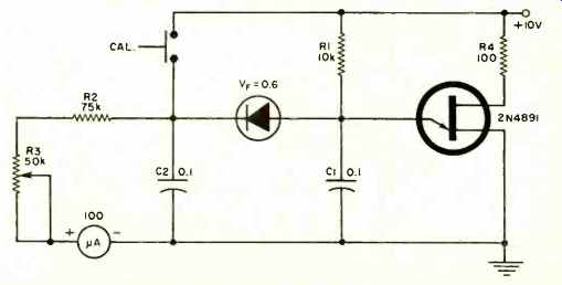
Fig. 2. Test circuit for UJT intrinsic standoff ratio.