PRINTED circuits and subminiature electronic equipment were P not in widespread use until the advent of World War II. War needs built an enormous demand for reduction in size of electronic assemblies of all types. One notable example was the "proximity-fuze shell," which exploded when it came within a certain distance of an object. The vast quantities of shells required stimulated research on new high-volume mass-production techniques in electronic circuitry. The combined talent of engineers' at the National Bureau of Standards and at the Centralab Division of Globe-Union Corp. brought about a very effective solution to the problem in the form of ceramic-based conducting circuits. From this early commercial-military development have stemmed innumerable advances in the art of printed circuitry and sub-miniaturization.
Although the work of the Centralab Co. was the first large-scale application, several foreign developments are worth mentioning.
As early as 1941 and 1942, Dr. Paul Eisler, working in England, applied for patents which involved the use of conventional printing techniques and photoengraving in electronics manufacture. One of these used etch-resistant ink as a printing medium.
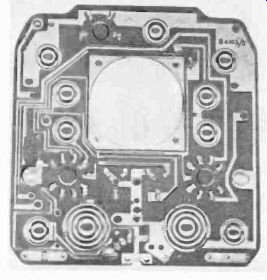
Fig. 101. Circuit plate used in an early British two-tube ac-dc receiver.
(Courtesy Sargrove Electronics, Ltd.)
The idea was to print the desired circuit on a metal foil and immerse the foil thus printed in an etchant which attacked all areas of the foil except those protected by the ink. Unfortunately, Dr. Eisler's work was mostly on a small scale and was not fully understood and exploited until the US Army Signal Corps became aware of it in 1946. Evidence of early printed-circuit work crops up in reports of the Joint Intelligence Objectives Agency, which investigated technical developments along these lines in Germany during and at the end of World War II. Various isolated techniques which might have inspired the current methods can be found in the patent literature, and among these is the Parolini patent granted in England about 1927 for the "production of electrically insulating plates with a series of connections."
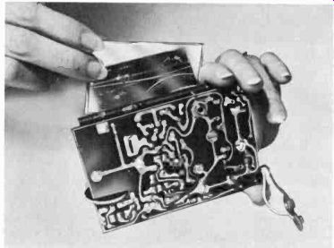
Fig. 102. Complete assembly (less case) for pocket portable receiver.
Important commercial developments
Perhaps the greatest advances in commercial printed-circuit and sub-miniaturization techniques are those concerned with mass-consumed goods. These encompass both domestic products such as used around the home and industrial equipment. The home products include radios, television sets, hearing aids, electronic music devices and automotive accessories. Industrial uses range from controls of all sorts to testing equipment such as the vacuum-tube voltmeter and cathode-ray oscilloscope.
Radios and printed circuits
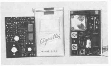
Fig. 103. This miniature radio is smaller than a pack of cigarettes.
One of the earliest mass-produced radio receivers employing ideas which later became useful in printed circuits and subminiaturization work was invented by J. A. Sargrove of England. A circuit plate for this unit is shown in Fig. 101. Produced in 1947, the radios were literally stamped out on a production line that required only two or three people to attend it. The capacitors on these plates were made by spraying zinc over concave indentations in the plastic base. Capacitances of 100 to 500 uuf were produced by corrugating the indentations, which gave a larger surface area. Plastic plates inserted at one end of the machine came out 20 seconds later, fully fabricated. Metal sockets for tubes and inductive components were inserted automatically and held permanently to the base plate by riveting and soldering. The finished plates were automatically tested and, if two plates in a row were defective, the machine shut down until repairs were made. The receiver was a two-tube unit designed for use in Asia and, some what like Eisler, Sargrove was a little bit ahead of the times.
From Sargrove's first attempts have come many practical modern receivers. Pocket radios such as the one shown in Fig. 102 have become common as a result of printed circuits and sub miniaturization.
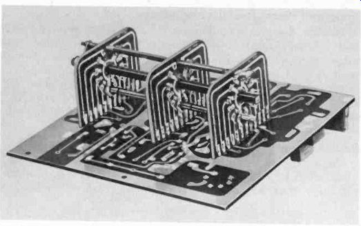
Fig. 104. A printed circuit bandswitch
used in an all band receiver. (Courtesy Allied Radio Corp.)
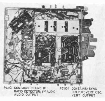
Fig. 105. Printed circuit plates find wide use in television. This set combines
conventional wiring techniques with the use of printed circuitry. (Courtesy
RCA.)
This receiver has a loudspeaker output. Still more remarkable is the unit shown in Fig. 103, smaller than a pack of cigarettes. Its circuit is a re-flexed superhet using four transistors and two diodes to provide a converter, two if stages, avc and avc-detector combination, and audio output to a magnetic earphone. The entire unit weighs 5 ounces.
The art of printed circuitry has been extended into the field of communications receivers ( Fig. 104 ). Printed circuits have made possible auto radios which can be removed from the dash board and used as portables.
Subminiaturization of radio devices has also been given tremendous impetus by the improved techniques in transistor production.
Television applications
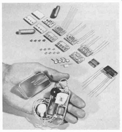
Fig. 106. Almost all of the circuitry of the hearing aid (bottom) is combined
in a single ceramic unit. Step by step construction of the amplifier is shown
in the upper portion of the photo. (Courtesy Centralab Corp.)
Printed circuits have also helped shrink the TV set down to where present-day 17- and 21-inch receivers occupy less volume than the early 5-inch sets. Fig. 105 shows the use of printed circuits in TV set construction. Front-end tuners and if stages have been some of the most common sections of TV receivers to employ this technique, entire if strips having been built up this way. Modular construction, described in Section 3, has been utilized in some sets to make maintenance easier.
Hearing aids
Before the advent of the modern hearing aid, batteries had to be carried separately in bulky cloth "aprons" worn on various parts of the body, or else as a cumbersome battery-pack in one pocket. The older hearing aids also required a cord from the battery to the amplifier and another cord connecting the amplifier to the earpiece. These units commonly ran to 5 and 6 inches on a side and over 1 inch thick.
One of the earliest firms to experiment with printed-circuit and subminiaturization techniques in the hearing-aid field was the Allen-Howe Electronics Corp. In cooperation with Centralab, it developed several designs based on a few fundamental amplifier circuits. After much experimental testing, the ceramic circuit plate ( Fig. 106) was developed that became the complete audio amplifier-heart of the hearing-aid chassis. This was the beginning of the end for scattered components which formerly were soldered in place by tedious hand work and elaborate mechanical assembly methods. The chassis was built up to include a volume control plate and battery holder.
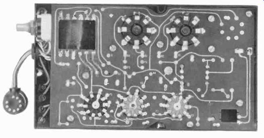
Fig. 107. Bottom view of a printed-circuit industrial amplifier. (Bristol
Co.)
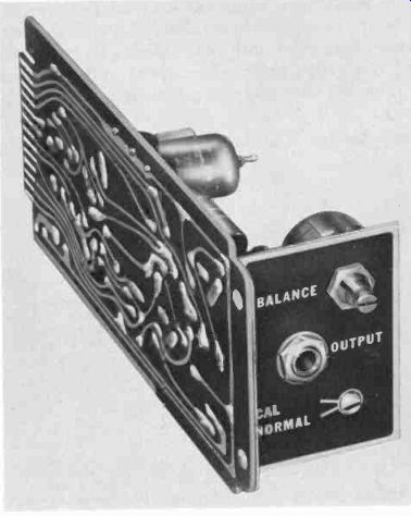
Fig. 108. A control unit used in conjunction with test instruments. The characteristics
of a test setup are changed simply by substituting a different unit. (Swartwout
Electronics Co.)
An added advantage of printed-circuit hearing aids is that smaller high-energy-low-volume batteries can be used to make lighter, less-conspicuous devices, and give longer battery life.
Present-day repair work on hearing aids often amounts to no more than replacing a single printed-circuit plate in a few minutes' time. Here again the transistor helped shrink a product to incredibly small size.
Today, through the use of transistors, printed circuits, and sub-miniaturized components, it is possible to manufacture hearing aids the size of book matches, and even units which are self-contained and will fit into the ear! Single-stage amplifiers the size of pencil erasers and a four-stage transistor audio amplifier not much larger in volume than a cigarette are described in later sections.
Industrial electronics uses
Printed circuits have found their way into amplifiers used in control circuits, test instruments and computers. An example of industrial printed circuitry is the amplifier chassis shown in Fig. 107. One of the common uses is where the range or input conditions of an instrument have to be changed quickly by inexperienced personnel. One instrument company has made up various forms of controllers based on this idea. If the characteristics of the process require a change in the mode of control, the opera tor merely substitutes a new printed-circuit board ( Fig. 108 ).
Fig. 109 shows examples of printed-circuit strain gauges.
Gauges like these have been made about the size of a match head. They are cemented to mechanical parts such as building beams, automobile axles and motor shafts. By measuring the resistance of the gauge under stress, load and strain can be determined. The fine wire patterns are made possible by photo-etching methods.
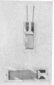
Fig. 109. These simple strain gauges find wide industrial application. They
are easily attached to parts being tested.
Switching devices of all kinds have been made using this approach. Printed-circuit commutators are easier to manufacture and require less hand-assembly work.
Musical devices
The basic building block in an electric organ is the tone generator, usually some form of oscillator. Because of the repeated circuitry found in electronic organs, printed-circuit techniques naturally lend themselves to such applications. Another fundamental circuit in electronic organ manufacture is the modulator, and several articles have appeared in popular magazines on the use of printed circuits in this connection. One of the nicer features of organ building is that relatively few components are needed in the basic building-block circuits, and printed circuitry minimizes the time required to manufacture and wire the basic units.
Advantages of printed circuits and sub-miniaturization
These new techniques offer many advantages:
1. Reduced cost in wiring.
2. Adaptability to both large and small quantity production.
3. Savings in space and weight.
4. Reproducibility-uniformity from one unit to the next.
5. Ease of testing and replacement.
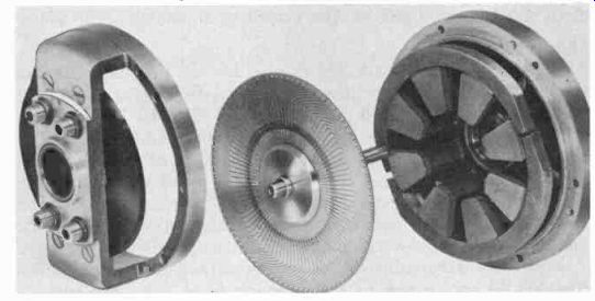
Fig. 110. This printed-circuit motor has been disassembled to show the armature.
(Photo courtesy Photo circuits Corp.)
From just looking at a printed-circuit board you can see that a tremendous amount of wiring labor is saved-the savings have been estimated to be as high as 35% to 60%. Wiring labor normally includes cable harnessing, wire stripping, and physically lacing the wires into place prior to soldering.
Space and weight savings often run as high as 100% over similar items using conventional wiring. If the sides of an assembly are reduced by one-half, the volume is reduced by one-eighth. Assuming uniform density throughout, the weight would also be cut by a factor of 8. Even with nonuniform density, the saving in weight is normally three or four times that of conventional devices.
Because the circuit has been laid out in advance on a master that has been checked and corrected, there is less chance for human error on individual chassis. If parts have to be positioned in certain locations, such as rf or high-gain audio circuits ( notorious for feedback troubles ), the printed circuit usually offers a better chance of fixing the location more accurately from chassis to chassis. Overall dimensions of the printed-circuit package can be held to closer tolerances than the wired type of unit in which hand labor is variable from person to person. Interchangeable plug-in units have a better chance of fitting if they are made in printed-circuit or module form.
Another advantage is that printed-circuit connections can be paralleled in manufacture with a set of lines made expressly for testing. This provides the service technician with easier access to the circuit, which might otherwise be difficult, if not impossible, due to wiring put on after certain components are in place.
The future
Mushrooming in growth, the printed-circuits field has supplied the electronics industry with some unusual developments.
One of these is the printed circuit motor shown in Fig. 110. The unit has a printed-circuit armature made from a two sided-laminate. The armature disc rides between magnets. Brushes of silver-graphite are spring loaded against the armature. Two of the advantages claimed for such a motor design are smooth torque output and relatively spark-free commutation. The magnetic circuit of the motor consists of several alnico permanent magnets arranged around the outside edge of the printed circuit rotor disc. Variations of the motor can be made which have "stepping action," very similar to a telephone stepping switch. Such printed-circuit motors hold great promise for more power in smaller, lighter weight packages.
Another development is the micro-miniaturization program which has been under way for a few years now. Recent announcements by RCA and the U.S. Army Signal Corps indicate component densities of 300,000 to 600,000 per cubic foot! This is a far cry from the present average of 100 to 500 components in a similar volume. The components are housed on modules which are ceramic wafers about 3/10 of an inch square and less than 1/64-inch thick. A side development of this technique is the photo etched transistor which would be made as one small flat sandwich, doing away with height-consuming electrodes. This would ultimately provide a transistor that would be about 1/4 the size of a postage stamp, and probably only three to four times as thick.