So far, we have discussed only the basic printed circuit and subminiaturization techniques themselves. The simpler circuits have also been described in detail. However, many of the more interesting applications are those relating to ham commercial and industrial uses. These applications are presented here in sufficient detail to enable the advanced reader to duplicate them successfully.
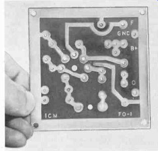
Fig. 701. Printed-circuit board for a crystal-controlled oscillator.
----------------
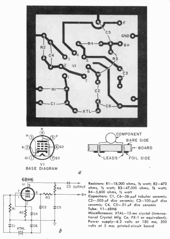
Fig. 702. The upper illustration (a) is a drawing of the printed-circuit board
for the crystal-controlled oscillator and shows the positioning of the parts.
Component leads are inserted from the opposite side (side without the foil pattern). F goes to 6.3 volts.
The lower illustration (6) is the circuit diagram of the oscillator.
Resistors: R1-18,000 ohms, 1/2 watt; R2-470 ohms, 1/2 watt; 13-47,000 ohms, 1/2 watt; R4-5,600 ohms, 1/2 watt
Capacitors: C1, C6-56-µµf tubular ceramic; C2-.005-µf disc ceramic; C3-100-µµf disc ceramic; C4, C5-.131-µf disc ceramic
Tube: V1-6BH6
Miscellaneous: XTAL-15- mhz crystal (International Crystal Mfg. Co. FX-1 or equivalent); Power supply-6.3 volts at 150 ma, 200 volts at 5 ma; printed-circuit board
------------------
Rf oscillator
Fig. 701 is a photo of a printed-circuit board for an rf crystal-controlled oscillator capable of operating from 200 khz to 13 mhz.
The unit is ideally suited for experimental laboratory work, for transmitter applications ( by addition of a powerful amplifier) and for general amateur use as a frequency standard. Fig. 702-a is a drawing of the board; Fig. 702-b is the schematic diagram.
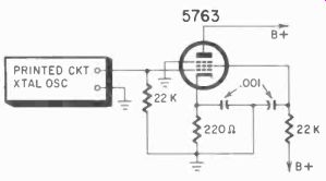
Fig. 703. Buffer amplifier which can be used to drive a power amplifier.
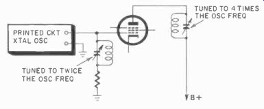
Fig. 704. The circuit following the crystal oscillator can be a frequency
multiplier.
Components are inserted through the board from the bare side, as shown in Fig. 702. Spread the component leads after inserting them through the board. This will hold the component in place and the soldering can be done from the foil side of the board.
Use a pencil type soldering iron, and as little solder as possible.
Excess lead wire should be cut off to make as much room as possible for the crystal holder and tube socket.
This modified Pierce oscillator will operate over a wide range of plate voltages. Designed for 210 volts of regulated dc, it can be capacitance coupled to other equipment. It can also be operated as a frequency multiplier by using a tuned grid circuit following the plate output of the oscillator.
Fig. 703 shows a buffer amplifier circuit for generating drive for a power amplifier. Another use for this type of circuit is that of a frequency multiplier ( Fig. 704 ). The frequency is doubled once in the grid circuit and again in the plate circuit giving an overall multiplication of four.
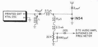
Fig. 705. A diode mixer can be used as an aid in making frequency measurements.
Fig. 705 shows a versatile circuit for frequency measurements up to about 500 mhz. Crystals in the 5-6-mhz range are handy for this purpose. Inductance L is tuned to the second harmonic of the crystal and higher-order harmonics are then compared with the transmitter frequency in the mixer circuit. The difference frequency, which appears between point D and ground, can be measured on a frequency meter, or the equipment can be set to zero with a known crystal standard while listening to the beat note with a pair of high-impedance phones. An audio amplifier will help in many cases.
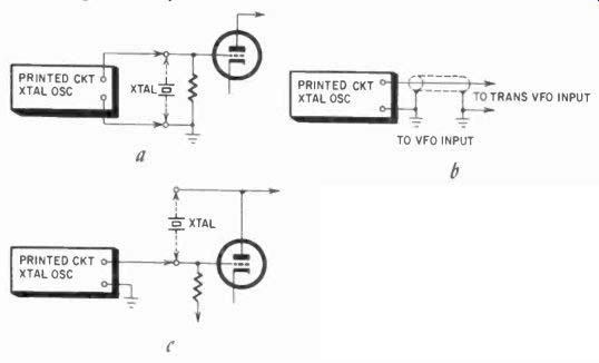
Fig. 706. The rf oscillator of Fig. 702 can be used to drive a transmitter.
The transmitter crystal is re moved or switched out of its circuit.
These diagrams show how the printed-circuit crystal oscillator can be connected to the crystal input, or to the vfo input, of a transmitter.
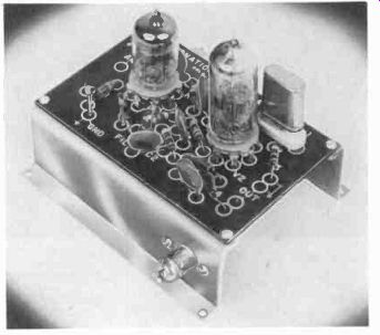
Fig. 707. Two-tube crystal-controlled converter.
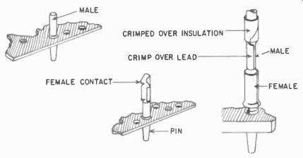
Fig. 708. Tubular pin connectors are used for making snap-on connections.
This oscillator can be used to drive transmitters through their external vfo connections or crystal sockets (Fig. 706 ). Several variations are possible depending on the nature of the existing crystal connections. The power supply required is 210 volts at 5 ma and 6.3 volts at 150 ma for the filaments. The rf output is be tween 3 and 10 volts with a load of 1,200 ohms.
As with all printed and miniature circuits, make tight connections at tube bases, socket pins and other key points. Mount all hardware firmly to the base and be sure to clip off excess wire after soldering.
-------------------
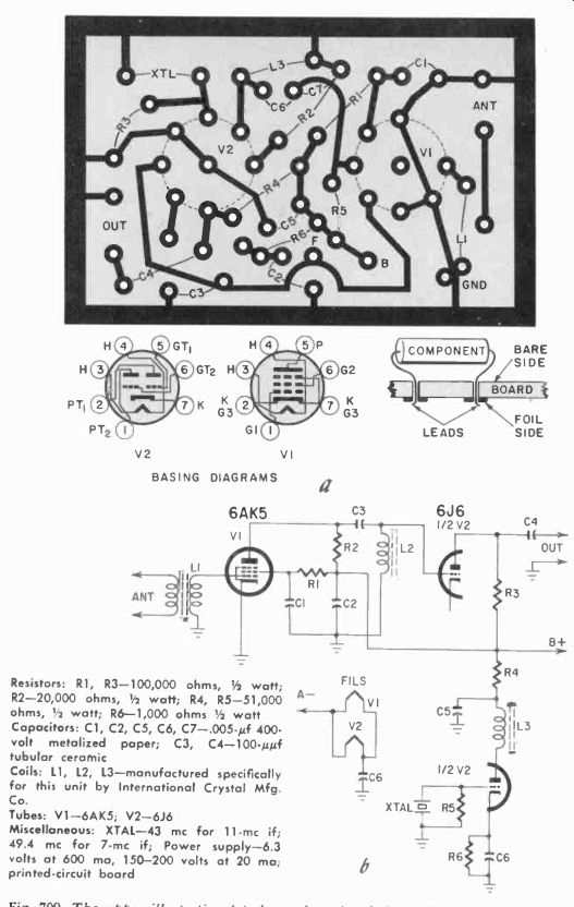
Fig. 709. The upper illustration (a) shows the printed-circuit board for the
crystal-controlled converter. The drawing shows the approximate positioning
of the parts.
The circuit for the converter (b) is shown below.
Resistors: R1, R3-100,000 ohms, 1/2 watt; R2-20,000 ohms, 1/2 watt; R4, R5-51,000 ohms, 1/2 watt; R6-1,000 ohms 1/2 watt
Capacitors: C1, C2, C5, C6, C7-.005-0 400-volt metalized paper; C3, C4-100-uf tubular ceramic
Coils: L1, L2, L3--manufactured specifically for this unit by International Crystal Mfg. Co.
Tubes: V1-6AK5; V2-6J6
Miscellaneous: XTAL-43 mhz for 11- mhz if; 49.4 mhz for 7- mhz if; Power supply -6.3 volts at 600 ma, 150-200 volts at 20 ma; printed-circuit board
---------------------

Fig. 710. Two tube wristwatch AM transmitter. (Courtesy National Bureau of
Standards)
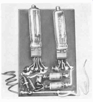
Fig. 711. Inside view of the wristwatch transmitter.
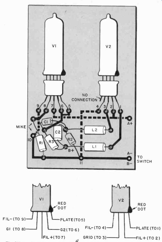
Fig. 712-a. The upper drawing shows how both tubes, their sockets, and the
various components are mounted on the printed-circuit board. The filament leads
are run on the underside of the board from 7 to 2 and then to A+; underside
connections are also run from 1 to the A-bus and from 9 to one side of the
mike. Crossovers are made by through-connecting wires 2. 7, 9, 10 and 11. The
values of the parts are given in the parts list on the facing page. Since the
tubes have symmetrical leads, a red dot is used for lead identification. This
is illustrated in the lower drawing.
----------------
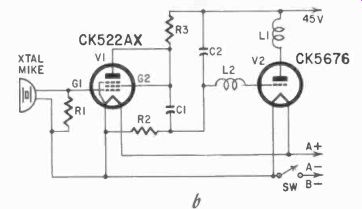
Fig. 712-b. Circuit diagram of the wristwatch transmitter.
Resistors: R1-5 megohms, 1/4 watt; R2 10,000 ohms, % watt; R3-50,000 ohms, 14 watt
Capacitors: C1-.01 0, 100-volt paper; C2 -.0001 0, 100 volt-paper
Tubes: V1-CK522AX; V2-CK5676 Coils:.1.1; L2
Miscellaneous: Crystal-type microphone; spst slid. switch (SW); 1.5-volt battery; 45-volt battery; printed-circuit board
----------------------
6-meter converter
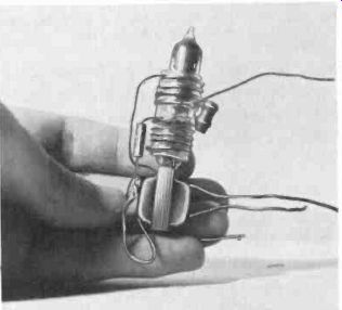
Fig. 713. Single-tube transmitter in which the tube acts as a form for the
oscillator coil.
Fig. 707 shows a very compact, broad-band, crystal-controlled converter which has an if output in two ranges-600 to 1,500 khz and 7 to 11 mhz. The frequency range is 50 to 54 mhz with a 51- mhz design center. The converter is about 4 by 3 1/2 by 3 1/2 inches overall, and its weight is a mere 3 ounces! In general, wiring procedures are much like those for the 15- mhz oscillator. One feature of this unit is the tubular pin connectors used for making snap-on connections to the printed-circuit board (Fig. 708). Two plugs are provided for connection to a 6-meter antenna. Most commercial receivers have accessory power sockets which can be used to power the converter, which takes approximately 180 volts de at 20 ma on the plate and 6.3 volts at 600 ma for the filaments. Fig. 709 shows the complete details of the converter.
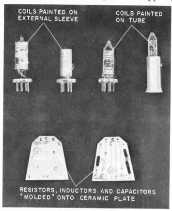
Fig. 714. Coils can be painted on a plastic form which is fitted over the
tube.
After the converter has been installed, operation is simple.
Converters having a 43- mhz crystal will cover an if of 7 to 11 mhz for the 50-54 mhz band. The 50- mhz point will appear at 7 mhz on the tuning dial of the receiver, and the 54- mhz point at the 11- mhz setting. With a 49.4-me crystal, 50 mhz will appear at 600 khz and 54 mhz at 4.6 mhz. The extent of the band coverage can be checked using an external high-frequency oscillator with appropriate crystals.
Checking the 6-meter converter
A grid-dip oscillator is one of the best instruments with which to check the converter. Operating the oscillator as a diode detector, check for converter crystal operation by tuning for radiated energy from the oscillator coil, L3. With the converter connected to the receiver, the grid-dip oscillator can be used as a signal generator for test purposes.
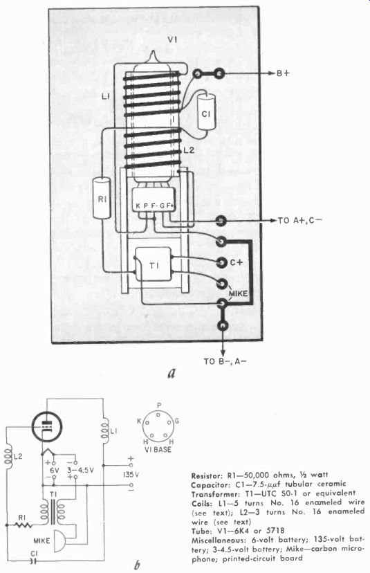
Fig. 715. Single-tube "lipstick" transmitter. The oscillator coil
is wound on a form which is then slipped over the tube.
---------
Resistor: R1-50,000 ohms, 1/2 watt
Capacitor: C1-7.5-/rµf tubular ceramic
Transformer: T1-UTC SO-1 or equivalent
Coils: 11-5 turns No. 16 enameled wire (see text); L2-3 turns No. 16 enameled wire (see text)
Tubs: V1-6K4 or 5718
Miscellaneous: 6-volt battery; 135-volt battery; 3-4.5-volt battery; Mike--carbon microphone; printed-circuit board
Be sure to check your receiver before expecting good results from the converter! Proper operation of the converter depends upon the receiver operating correctly. Check the receiver for pickup with antenna terminals open and the converter disconnected. Any signals picked up in the converter if range will show up as undesired signals when the converter is put back into operation.
Two-tube wristwatch AM transmitter
An early version of a two-tube printed-circuit radio transmitter, developed by Dr. Cledo Brunetti when he was with the National Bureau of Standards, is shown in Fig. 710. This transmitter was originally made using a ceramic base and silver-ceramic firing technique; the version in Fig. 711 can be made up by the experimenter, using modern copper-clad laminates.
Fig. 712 shows the layout and the schematic of this novel transmitter which has a range of about 200 feet, depending upon receiver sensitivity and the frequency chosen.
Transmitters such as this have been used for paging and also as remote mikes in industrial systems.
"Lipstick" transmitter
-----
Fig. 716. Layout of the printed-circuit board for a subminiature multivibrator.
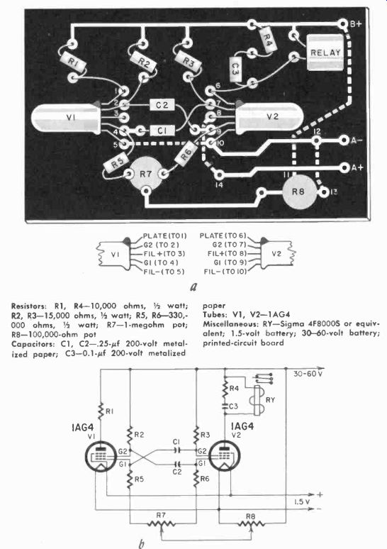
Fig. 717. The upper illustration (a) is a drawing of the printed-circuit board
for the subminiature multivibrator. The circuit (b) is shown below. Conductors
run from 11 to B+ on the underside of the board, and also from 12 to 13. Crossovers
are made by through-soldering with a piece of No. 20 tinned hookup wire. A-
also has a conductor on the opposite side from 5 to 10. A+ runs on the opposite
side from 3 to 14. Also, through-solder at points 5, 8, 10 and 1-1.
----------
Resistors: R1, R4-10,000 ohms, 1/2 watt; paper R2, R3-15,000 ohms, 1/2 watt; R5, R6-330,-
Tubes: V1, V2-1AG4 000 ohms, 1/2 watt; R7-1-megohm pot; RY-Sigma 4F80005 or R8-100,000-ohm pot client; 1.5-volt battery; 30-60-volt battery;
Capacitors: C1, C2-.25-uf 200-volt metal-printed-circuit board lied paper; C3-0.1-µf 200-volt metalized.
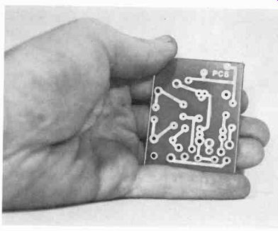
Fig. 718. Printed-circuit board for a two-tube radio-control receiver.
---------------
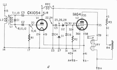
Fig. 719. Circuit diagram of the two-tube radio-control receiver.
Resistors: R1-5 megohms, 1/2 watt; R2- 10 megohms, 1/2 watt; R3-3,300 ohms, 1/2 watt; R4-50,000-100,000-ohm pot
Capacitors: C1-15-wif tubular ceramic; C2-150-uuf mica , C3-47-µµf tubular ceramic; C4, C6-.01-0 200-volt metalized paper; C5-.02-uf 200-volt metalized paper
Coils: L1-17 turns No. 20 enameled wire on 5/8-inch CTC form; L2-3 turns No. 20 dcc wire wound over L1; RFC-10 Ah
Tubes: V1-CK1054 or RK-61; V2-1AG4
Diodes: D1, D2-1N66
Miscellaneous: RY-Sigma 4F8000S or equivalent; Power supply-I.5 volts (filaments), 45 volts (B supply); printed-circuit board
----------------
Fig. 713 shows a transmitter in which the inductor pattern was silvered directly on the envelope of the tube. One practical version of this unit can be made by winding or painting the inductor around the tube. Another technique ( Fig. 714) is to wind or paint the inductor around a polystyrene tube which will fit snugly over the tube. All other components, such as capacitors, resistors and miniature matching transformers, can be soldered to each other and mounted on the polystyrene tube. The complete schematic of this transmitter, which normally operates above 50 me, is shown in Fig. 715.
Both of the foregoing miniature transmitters point up very dramatically the need for smaller batteries and power sources, since the transmitter units are about the same size or even smaller ( in the case of the-lipstick" transmitter) than the batteries needed to power them.
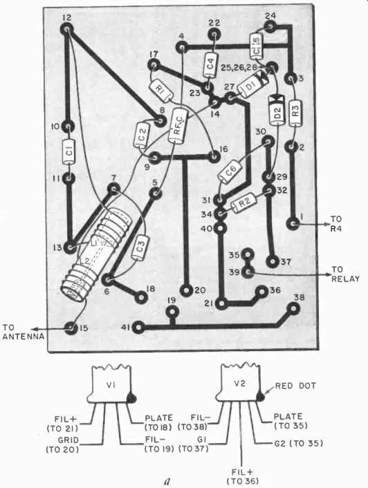
Fig. 719 (continued). Printed-circuit board for the two-tube radio-control
receiver.
Use spaghetti on tube leads where these might cross.
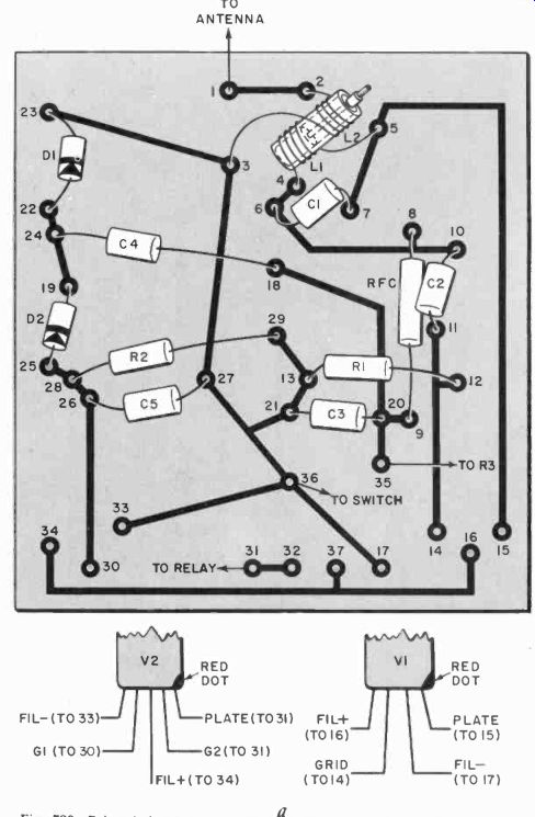
Fig. 720. Printed-circuit board arrangement (a) for the- Little Gem duo-diode
receiver.
----------------
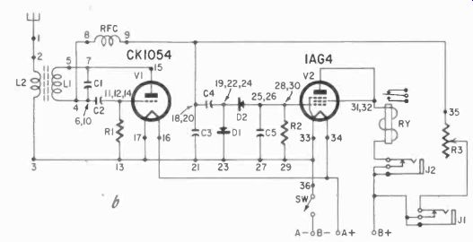
Fig. 720 (continued). Circuit diagram of the Little Gem receiver.
Resistors: R1, R2-10 megohms, 1/2 watt; R3-100,000-ohm pot
Capacitors: C1-6.8-uuf tubular ceramic; C2--51 uuf tubular ceramic; C3, C5--01-µf midget paper; C4-.02-uf midget paper
Coils: 11-17 turns No. 20 enameled wire on 5/8-inch-diameter slug-tuned form; 12 3 turns No. 20 dcc wire wound over L1; RFC-50 Tubes: V1-CK1054 or RK-61; V2-1AG4
Diodes: D1, D2-1N66
Misc. RY Sigma 5F or equivalent;
J2-closed-circuit jacks; 1.5-volt battery; 45-volt battery; printed-circuit board
-------------------
Adjustable frequency and pulse-width multivibrator
Fig. 716 is a printed-circuit board for a subminiature multivibrator having a pulse frequency range of 2 to 10 pps (pulses per second) with the circuit values shown in the diagram in Fig. 717. The pulse-width ratio is normally 20/80, but can be changed by altering the circuit constants.
The circuit, as originally designed, used conventional 3V4 tubes, but the subminiature type IAG4 has been substituted for space and current savings without sacrifice in performance. Any relay of 3,000 to 10,000 ohms will work out well in the circuit. The 100,000-ohm potentiometer controls the frequency from 2 to 10 pps and, by lowering the 0.25 pf capacitors to about 0.1, the pulsing rate can be increased to 20 or 30 pps. Lowering the 330,-000-ohm resistors will extend the pulse-width ratio from 20/80 nearer to 0/100. Among popular uses for this unit are radio-control proportional-control systems and remote positioning devices.
Printed-circuit radio-control receivers
Printed circuits and subminiature techniques have been applied successfully to radio-control receivers, a few of which are detailed here.2 The experimenter may construct these units from regularly available parts, but is cautioned against possible patent infringement if units are mass-produced for resale.
[2. Many of these circuits are put out in kit form by the Ace Radio Control Co., Higginsville, Mo.]
Lorenz two-tube receiver
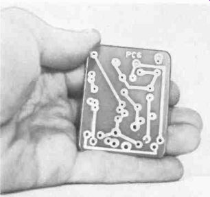
Fig. 721. Photo of a printed-circuit board used for the Little Gem receiver.
Fig. 718 shows the printed-circuit board for the unit which is especially well-suited to model-plane use. The potentiometer and sensitive relay are mounted in a plastic case or on a separate mount.
Soldering can be done in any order. Using a pencil-type soldering iron and a good grade of rosin solder, solder components in place by bending leads up, one at a time, and carefully making the solder joints at the copper base strip. Cut off any excess lead after each joint has been made. Where an eyelet is used, make a solder connection between both the eyelet and the copper strip for firm electrical contact.
Be sure to solder coil windings to the soldering lugs on the coil form and also solder the flea clips to the copper to insure good contact.
It is very difficult to solder these small assemblies with a conventional iron, and an investment in a midget pencil-type iron is a wise one.
When all components have been soldered, check the top of the base and use a needle file to smooth gently and carefully any sharp edges left by the cutting pliers. Cover the spot where the tubes will rest with electrical tape or several coats of a good insulating lacquer. If desired, tubes can be cemented in place after insertion by using a good grade of rubber cement on the tube body. The battery and relay leads to the receiver should be color-coded for easy troubleshooting. The complete hookup is shown in Fig. 719.
Test the assembled unit as follows: Insert V1 only. Plug a 0-5-ma test meter into meter jack 1, and make sure the potentiometer is set at maximum resistance. Turn on the filament switch. The meter should read about 0.1 ma and also be a little unsteady, an indication that the set is super-regenerating. If a headset is avail able, it can be inserted in series with the meter and a loud hiss should be heard. If there is no hiss, check all solder joints very carefully and also recheck wiring, point by point. The set must super-regenerate to work right. While the set is super-regenerating, turn on the transmitter and key it. Tune the receiver slug until a sharp dip in current is observed. This dip should go down to .02 ma or even less.
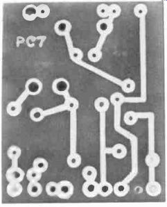
Fig. 722. Photo of the printed-circuit board for the Gazistor receiver.
Now insert V2. Be sure to follow the tube base connections carefully, matching up the proper connections with the little red dot on the base of the tube. The two leads nearest the red dot are the plate and screen grid. Both go into the same flea clip at point 35. Insert the meter in meter jack 2. With the first stage at 0.5 ma, the second stage should draw close to zero current. With both tubes working, the second stage should jump from 0 to 2 or 3 ma when the transmitter is keyed, depending upon relay resistance and tube type in the second stage.
The distance check should be made at 200 yards or so. The meter should be only in jack 1 for this test.
Battery voltages should be watched closely, since a B-voltage below 41 and an A voltage below 1.2 will make operation very unsteady.
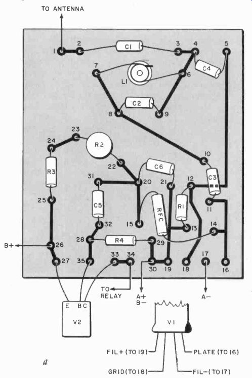
Fig. 723. Printed circuit board arrangement for the Gazistor receiver. Use
spaghetti on leads where these cross the circuit pattern.
---------------
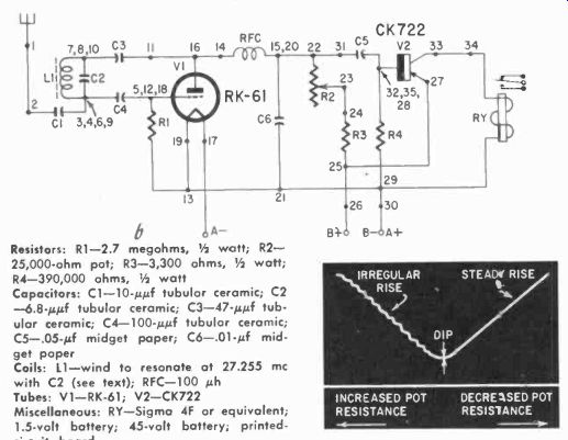
Fig. 723 (continued). Circuit of the Gazistor receiver. The graph represents
the plate current of the RK-61 for different settings of the potentiometer.
Resistors: R1-2.7 megohms, 1/2 watt; R2 25,000-ohm pot; R3-3,300 ohms, 1 1/2 watt; R4-390,000 ohms, 1/2 watt
Capacitors: C1-10-µµf tubular ceramic; C2-6.8-µµf tubular ceramic; C3-47-µµf tubular ceramic; C4-100-µ0 tubular ceramic; C5-.05-0 midget paper; C6-.01-0 mid get paper Coils: L1-wind to resonate at 27.255 mhz with C2 (see text); RFC-100 uh
Tubes: V1-RK-61; V2-CK722
Misc: RY Sigma 4F or equivalent; 1.5-volt battery; 45-volt battery; printed-circuit board
--------------
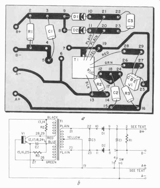
Fig. 724. Layout of the printed-circuit board and circuit diagram for a transistor
converter.
Resistors: R1-100,000 ohms, 1/2 watt; R2, R3-1,500 ohms, 1/2 watt
Capacitors: C1-5-µf 50-volt electrolytic; C2- 50-volt paper; C3-.001-0 150-volt paper
Transformer: T1-see text (Ace Radio Control)
Transistor: V1-2N185 or 2N233
Diodes: D1 D2-1N66
Miscellaneous: 1.5-3-volt power supply (MD text)
---------------
Little Gem duo-diode receiver
This receiver incorporates a set of diodes between the first and second stages ( Fig. 720 ). One version of the printed-circuit board layout is shown in Fig. 721.
To test the unit, hook it up as shown in the schematic ( Fig. 720) and insert V1 only. A meter inserted in meter jack 1 should read about 0.1 ma and waver a little bit due to superregeneration.
A headphone check can also be made for hiss. If the set does not superregenerate, advance the potentiometer slightly to see if a current drop can be obtained and superregeneration started.
In most cases, failure to superregenerate can he traced back to poor or improper connections.
With the set superregenerating, key the transmitter and tune the receiver slug for a sharp current dip to nearly zero. Key the transmitter several times and make sure the slug is tuned properly for the dip. Now insert V2, checking to he sure base connections are matched properly. It is a good idea to put a dab of red model dope or red nail polish on the receiver base near the matching socket connection.
Insert a 0-5 ma meter in meter jack and then check both stages. With the first stage idling at 0.1 ma, the second stage may have a tendency to "jump" once in a while to a high current reading. Advance the pot until this tendency disappears. This is the minimum operating point for your particular receiver. The pot should be advanced slightly beyond this so that lowering battery voltages will not trigger the second stage unexpectedly.
The distance check is about the same as for the previous receiver, care being taken to check the battery voltages under load.
This receiver usually does not require tuning constantly, but it is a good idea to make a distance check before putting the model through its paces.
Gazistor receiver
The major feature of this receiver is the transistor second stage ...
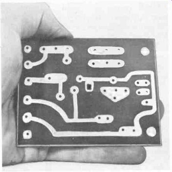
Fig. 725.
Photo of the printed-circuit board for the transistor converter.
... which helps reduce the space requirements. Fig. 722 is the printed-circuit board layout and Fig. 723 is the schematic. This unit will produce a slightly higher reading in the second stage than the first two receivers described, depending on how "hot" the transistor is.
Test by inserting V1 and plugging the meter into the single jack. Vary the 25,000-ohm potentiometer until the meter indicates 0.6 ma or thereabouts, and then turn on the transmitter.
Adjust the receiver slug until the meter drops to 0.1 ma or less when the transmitter is keyed. Turn the switch off and then plug in the transistor. Be sure the switch is turned off when inserting or removing the transistor. Because transistors vary widely in characteristics, you should get a reading of 1 to 3 ma when the switch is turned on again.
Readjust the potentiometer for a reading of 0.8 to 1 ma. Now, when the transmitter is keyed, the meter should rise to 4 or 5 ma, depending on the quality of the particular CK722.
If the idling current ( no transmitter signal) can't be cut down to 1.5 ma or so, increase the 390,000-ohm resistor to 470,000.
Sometimes it is necessary to run this resistor up to about 800,000.
If the resistor is increased, a check of signal-on current should be made to see the value to which the current jumps. If the idling current is within the range mentioned, and a greater signal-on current increase is desired, the 390,000 ohms can be reduced slightly. Fig. 723 shows the action of the potentiometer, with the solid line representing the current reading on the meter. As you go toward higher resistance on the pot, the meter reading will increase in a jerky manner; toward lower resistance, there will be a smooth current increase. The best setting is slightly beyond the dip, on the steady-current side.
It is a good idea also to install a dpst switch in this unit, since the steady transistor current will run the batteries down unless both B-plus and B-minus are opened.
B-supply (transistor converter)
Fig. 724 shows details of a 45-volt B-supply which uses a single transistor feedback oscillator.
The transformer is the most critical component, and a ready made unit is readily available at nominal cost. The ratio of the collector winding to the emitter ( feedback) winding is approximately 9 to 5, and the winding procedure is too tricky for the home builder to do himself. Other ratios will produce erratic oscillator starting under various loads or else no starting at all.
The ratio shown gives consistent starting under full load. Regulation is achieved with a center-tapped secondary, shunted by a 0.001-pf capacitor. Each outside leg of the transformer secondary feeds a diode.
An additional jumper puts the 4.5-volt battery ( three penlight cells in series) in as a boost on 3-5-ma loads. The 4.5-volt boost is cut out on lighter loads in the range of 1 to 3 ma.
The oscillator runs at about 6,000 cycles, and a 5-pf filter capacitor smooths the B-voltage output to the load. The unit can put out 5 ma at 45 volts with a 4.5-volt A-supply, or 30 volts at 3 ma with a 3-volt supply.
Fig. 725 is a photo of the actual printed-circuit board.