HAVING mastered the basic techniques of printed circuitry and learned how to select circuit components, you are ready to try a few simple circuits. The assemblies and techniques in this section have been chosen for their simplicity so that the builder can gradually acquire the feel of working with printed circuits.
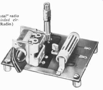
Fig. 601. A one-transistor "crystal" radio
receiver which employs printed circuitry. (Courtesy Allied Radio.)
Some of the projects use commercial subassemblies only; it would be impractical and too time-consuming for the average person to build them up himself.
One-transistor radio
Fig. 601 illustrates one of the basic applications of printed-circuitry: a one-transistor "crystal" set put up in kit form. The circuit pattern and schematic (Fig. 602) for the set can be easily duplicated by silver or copper painting or by simple etching with asphaltum- ferric chloride techniques. The construction procedure given is that used in assembling the commercial kit, but a home-made unit could be put together in a very similar manner once the printed-circuit board is made.
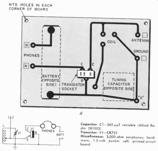
Fig.
602. The printed circuit pattern and schematic of the radio shown in Fig. 601.
Capacitor C1 grounds at hole "X" by means of a mounting screw. Phones
plug into terminals marked N.
----------
Capacitor: C1-365-AO variable (Allied Radio 281003)
Transistor: V1-CK722
Miscellaneous: 3,000-ohm earphones; hardware; 1.5-volt penlite cell; printed-circuit board
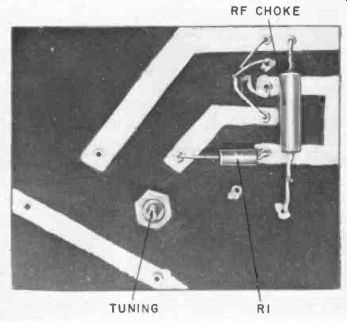
Fig. 603. Under chassis view of a one-tube thyratron receiver.
The first step is to assemble the necessary tools. For simple circuits, the following are recommended: diagonal cutting pliers, needle-nose pliers, large and small screwdrivers, 25- or 35-watt pencil type soldering iron and rosin-core solder. The next step in any printed-circuit kit assembly is to study the plans carefully and set up the necessary components in the order and place in which they are used. For a home-made "crystal" set, a plan or sketch should be drawn up as a guide before starting construction.
The procedure below is that suggested by Allied Radio for assembling their transistor kit:
1. Examine the printed-circuit board. Notice that one side of the board is printed with the name of the parts and components which will be mounted on the board. The other side has the printed-circuit pattern on it. In the case of a home-made board, the builder can either paint or rubber-stamp identifying marks on the board to help him in the assembly.
2. Examine the transistor socket. Notice that there are two holes together at one end of the socket, and the third hole is by itself at the other end of the socket. Push the socket into the board so that the end of the socket with the two holes is toward the words "ground" and "antenna."
3. Solder each of the three small prongs in the socket to the printed-circuit pattern. The two prongs closest together go to the B (Base) and E (Emitter) connections on the printed-circuit board, and the third prong goes to the C ( Collector) connection on the printed-circuit pattern. Do not overheat the printed-circuit pattern and blister the copper foil.
4. Mount the spade bolt on the front of the tuning capacitor.
This is done with a short machine screw. The hole in the capacitor is threaded, so no nut is required. The tuning capacitor is then mounted on the printed-circuit board in the space marked "tuning capacitor." Insert the spade bolt through the hole and tighten a nut over it. Insert two of the small screws through the two terminals on the side of the capacitor. Tighten a small nut over each screw. Turn the shaft of the tuning capacitor so that the plates are meshed and fully closed. Loosen the setscrew in the tuning capacitor knob. Slide the knob on the shaft as far as it will go; tighten the set-screw.
5. Put a "foot" on each corner of the printed-circuit board. These feet are internally threaded collars that raise the board off the printed-circuit side and prevent short-circuiting of the board if it is accidentally placed on a conductor.
6. Cut the transistor leads very carefully so that they are each 1/2 inch long. When cutting the leads, do not twist or bend them too much-they will break if treated roughly. Place the transistor in the socket. If the transistor is the type with two of the leads very close together, just put it into the matching holes in the socket. If the transistor is marked with a colored dot, the lead at the same side as the colored dot is the same as the lead which is widely spaced on the other type of transistor. If there is any doubt about the transistor markings, check the connections very carefully in the manufacturer's data sheet and match up the emitter, base and collector connections accordingly.
7. Insert the battery in the clips. Make sure it is polarized properly for the circuit.
8. Insert the three prongs of the tuning coil in the three holes in the board, and solder all of the coil prongs to the printed wiring pattern.
9. Hook up the antenna and ground, using a good antenna (50 feet long and about 50 feet high) and a good ground ( a cold-water pipe or a rod driven 4 feet into the earth 1. Use a lightning arrester in the antenna lead for safety.
Testing the one-transistor set
Plug the headphones into the holes provided. This will automatically complete the circuit and turn the set on. A 5,000-ohm headset is recommended. Rotate the tuning capacitor slowly you should hear several stations. The nearby stations will be strong and clear. If they do not come in check all the wiring on the board. Be sure the transistor is in properly and that the connections are firm. Reversed connections can damage the transistor and will certainly prevent reception. Unplugging the head set will shut off the set. Useful battery life in sets of this type is almost equal to the battery's shelf life.
One-tube radio-control receiver
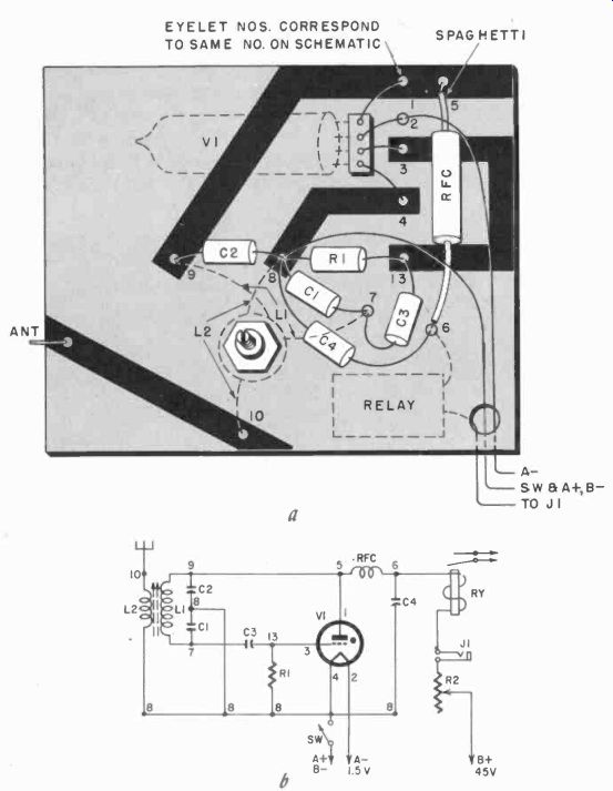
Fig. 604. The printed-circuit pattern (rear view) and schematic of the receiver
shown in Fig. 603. The tube, relay and coils (LI and L2) are mounted on opposite
sides of the board. The batteries, switch, jack and R2 are mounted separately.
Wires from eyelets #2 and #8 should be plastic-insulated type.
--------- Resistors: R1-2 megohms, 1/2 watt; R2 25,000-ohm pot
Capacitors: C1-47 µ0; C2-15 uµf; C3 100 uuf; C4-.02-0 200-volt paper
Coils: 11-15 turns No. 26 enameled wire on %-inch-diameter slug-tuned form; L2 3 turns No. 26 hookup wire wound over L1; RFC-10 kih
Tube: V1-RK-61 or CK1054
Miscellaneous: RY-8,000-10,000-ohm relay (Sigma 4F, 26F or equivalent); 5-spst toggle switch; closed-circuit lack; 13-volt battery; 45-volt battery; printed-circuit board
Fig. 603 shows the underside of a one-tube gas-filled thyratron receiver using printed-circuit techniques. The procedure was to paint the conductors on the underside of the board and mount the bulkier components such as the tube, coil and relay on top.
The circuit was developed by E. Lorenz and is sometimes known as the Lorenz 61. The assembly is made using Fig. 604 as a guide.
Paint the conductors on the underside of the board with silver paint and allow the board to dry. A 1/16-inch-thick Bakelite board was used in this case. Next, drill out No. 5.3 holes and rivet eyelets in place.
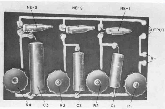
Fig. 605. This unit uses neon bulbs as liming devices.
After the riveted assembly is completed, add the components as follows: Cut out a rectangular hole for a subminiature four-pin tube socket, as shown. The opening for this socket should be cut slightly undersize so the socket fits snugly. Add a few drops of Duco cement around the edges of the socket if necessary. Using a 25-watt pencil soldering iron, solder the lugs to the. identically numbered eyelets, making sure all leads are in place. Starting with tube pin 1, one end of the 10-ph rf choke is connected to eyelet 5. The other end of this choke goes into eyelet 6. Insert the A-minus lead in socket eyelet 2. Next, make sure tube-socket pin 3 is in eyelet 3. The switch lead for A-plus and B-minus should be in socket eyelet 8.
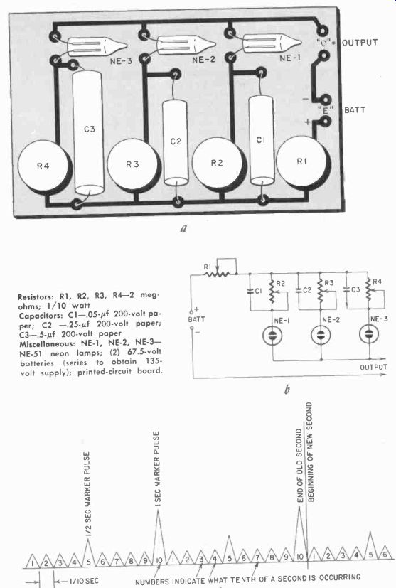
Fig. 606. Circuit diagram and arrangement of the printed-circuit board (front
view) of the chronograph neon timer.
The illustration at the bottom is the time- scale pattern of the neon timer.
------
Resistors: R1, R2, R3, R4-2 meg ohms; 1/10 watt
Capacitors: C1-.05-0 200-volt paper; C2-.25-0 200-volt paper;
C3-.5-µf 200-volt paper
Miscellaneous: NE-1, NE-2, NE-3 NE-51 neon lamps; (2) 67.5-volt batteries (series to obtain 135-volt supply); printed-circuit board.
The next components added are the resistors and capacitors.
The 2-megohm resistor R1 is placed between eyelets 8 and 13.
The 100- uuf capacitor C3 is laid between eyelets 7 and 13.
Capacitor C1, a 47- uuf unit, is put between eyelets 7 and 8, and C2 (15- uuf ) between 8 and 9.
Note-that eyelets 4 and 8 act as a common A-plus, B-minus return.
Capacitor C4 is connected between eyelets 6 and 8.
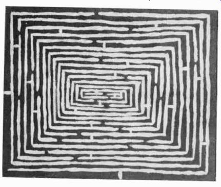
Fig. 607. .4 printed-circuit maze makes an interesting game.
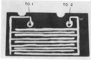
Fig. 608. This printed-circuit maze is used as the sensing element of a rain
detector.
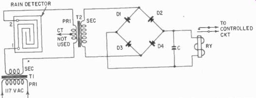
Fig. 609. The rain detector employs a bridge rectifier to trigger the relay.
----Capacitor: C-.002-µf 200-volt paper
Transformers: T1-117-volt primary, 6-10- volt secondary (doorbell type); T2-500-ohm primary, 50,000-ohm secondary (Stancor TA24 or equivalent)
Diodes: D1, D2, D3, D4-Conant meter rectifier type M, series 500 or 4 11434's in a bridge.
Misc. RY Sigma 4F80005 or equivalent; printed-circuit board
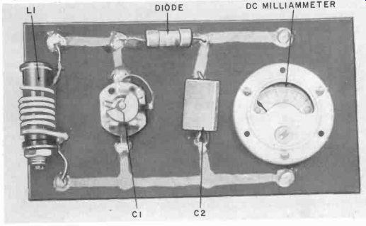
Fig. 610. A field-strength meter can be easily made using etched-circuit techniques.
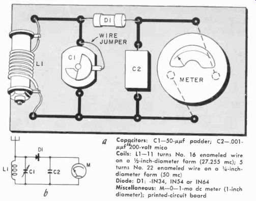
Fig. 611. The printed-circuit pattern and the schematic for the held-strength
meter shown in Fig. 610.
---------
Capacitors: C1-50-µgf padder; C2-.001-µµf 200-volt mica
Coils: L1-11 turns No. 16 enameled wire on a 1/2-inch-diameter form (27.255 mhz); 5 turns No. 22 enameled wire on a 1-inch-diameter form (50 mhz) Diode: D1-IN34, IN54 or IN64
Miscellaneous: M-0-1-ma dc meter (1-inch diameter); printed-circuit board
Coil assembly L1-L2 is mounted in a 1/4-inch hole at right angles to the base, and the leads are brought down to eyelet 7 and 9 for L1, and 8 and 10 for L2. The B-plus side of the relay goes through a jack and a 25,000- or 50,000-ohm subminiature pot ( not shown in the pictorial) and then to the battery supply.
The battery supply consists of a size D 1.5-volt cell for long life of the filaments and two 22.5-volt Burgess K-15 B units for the high voltage to the plate of the RK-61.
To tune the unit, insert a 0-5-ma meter in the jack in series with the B-plus lead. Be sure that the 25,000- or 50,000-ohm potentiometer is turned to maximum resistance before turning on the A-plus-B-minus switch. The meter should read between 0.5 and 0.8 ma. A Sigma 4F relay was used and set to pull in at about 0.9 ma. Turn on the 27.255- mhz carrier from the transmitter, and key it. With the transmitter keyed, tune the core of the coil L1-L2 until you see a sharp dip to 0.2 ma or less. Field-check the receiver at 500 yards or so with a friend.
Chronograph neon timer In this timer (Fig. 605) a neon lamp is charged and discharged through an R-C timing circuit. Basically the unit is a set of relaxation oscillators with component values chosen to give neon flashes at 1/10-, 1/2- and 1-second intervals. If the bulbs were placed side by side and mounted so that their flashes fell on a moving photographic film or paper, the unit would put a time scale on the film similar to that in the lower portion of Fig. 606. The bulb circuits must be adjusted individually, and the battery circuit has a 2-megohm series potentiometer to take care of changes in battery voltage and to synchronize the 1/2- and 1-second pulses.
Note the symmetry in the printed circuit layout of Fig. 606 which closely resembles the schematic. Again, silver paint was used in the construction, although an etched circuit would have been about as easy to set up.
Printed-circuit maze
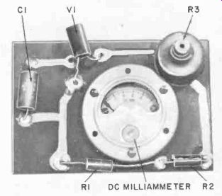
Fig. 612. A printed circuit amplifier which uses a single transistor.
One interesting device which can be made using printed-circuit paints is the game shown in Fig. 607. This is a maze, which is used in series with a low-voltage battery and relay. The secondary contacts of the relay are hooked up to a bell or buzzer, and one side of the circuit goes to the maze, which is a common ground; i.e., all its parts connect to each other. The other side of the circuit goes to a test prod with a phono needle in the chuck of the prod.
The object of the game is to see who can run the test prod from the outside to the inside of the maze in the shortest length of time without ringing the bell or buzzer.
The maze can be silk-screened and made up in larger quantities by the etch method if desired. For finer results in the "hand-painted" model, use a 000 or 0000 sable paintbrush, and thin the silver or copper paint accordingly. The resistance in series with the relay and battery is adjusted to close the circuit when the prod contacts the maze and yet limit the current to a safe value in the relay coil.
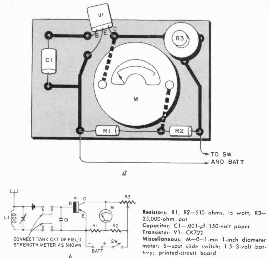
Fig. 613. The printed-circuit pattern and schematic of the simple amplifier.
Note that this unit can be used with the .field-strength meter.
----------
Resistors: R1, R2-510 ohms, 1/2 watt; R3 25,000-ohm pot
Capacitor: C1-.001-0 150-volt paper
Transistor: V1-CK722 s:
Misc. M-0-1-ma 1-inch diameter meter; 5-spst slide switch; 1.5-3-volt battery; printed-circuit board
Rain detector
Fig. 608 shows a variation of the maze game in which a painted silver grid with two parallel lines has been used as a moisture detector. Terminals 1 and 2 are hooked up to. the input of a low-current sensitive relay circuit (Fig. 609 ). The output of the relay can be connected to an alarm to signal rain or humid conditions. The plate should be mounted in a spot where it will receive only light rainfall, such as a window ledge on an inside wall. Another method is to mount the detector plate inside a perforated plastic box, drained by sloping the box sideways.
Field-strength meter
A handy unit to make up in printed-circuit form is the etched-circuit version of the field-strength meter shown in Fig. 610. As with all simple printed circuits, the schematic in Fig. 611 bears a striking resemblance to the finished product. To take advantage of the subminiature layout, an 0-1-ma 1-inch-diameter meter was used as the indicator. An antenna can be made from a 2- or 3-foot piece of piano or brass wire, fastened to the unit with a banana plug and jack combination. The entire unit can be used in the form shown or mounted in a small meter box since no batteries are required.
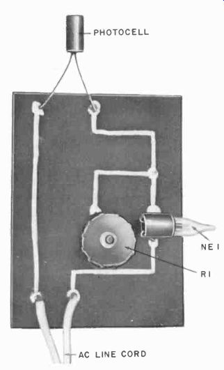
Fig. 614. This photoelectric light meter is built up using etched-laminate
techniques.
To use the field-strength meter, set it at a fixed distance from the transmitter or rf source being checked. Key the transmitter and tune it for the greatest needle swing on the dc milliammeter.
Leave the tuning capacitor setting alone and then go back to the transmitter, making whatever changes are necessary in the antenna, crystal coupling, etc. of the transmitter to get optimum performance. The printed-circuit transistor amplifier can be added to the field-strength meter to secure more sensitivity.
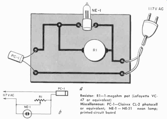
Fig.
615. The printed-circuit pattern and schematic of the light meter shown in
Fig. 614.
---------- Resistor: R1-1-megohm pot (Lafayette VC-47 or equivalent) Miscellaneous: PC-1-Clairex CL-2 photocell or equivalent; NE-1- NE-51 neon lamp; printed-circuit board
Printed-circuit amplifier
Figs. 612 and 613 show a printed-circuit amplifier built up with etching techniques. Carbon-composition resistors were used. The 25,000-ohm control is a subminiature pot, and the voltage supply is two Mallory RM-625 mercury cells in series, Scotch-taped together to form a battery. The circuit has an approximate current-amplification factor of 10, so that an 0-1-ma meter will now be effectively an 0-100-microampere meter. When using this circuit with the field-strength meter above, hook it up as shown in Fig. 613. Switch on the battery and zero the meter with the 25,000-ohm pot. Then tune the field-strength meter.
Photoelectric light meter
Fig. 614 shows a photo light meter fabricated by etched laminate techniques. The photocell is in series with a neon lamp and 117 volts ac is fed to it. A 1-megohm pot shunts the neon lamp and serves as a sensitivity control. The light source to be measured is set to shine on the photocell, and then the potentiometer adjusted to a point where the neon lamp just lights. Another way to use the meter is to put a set of polaroid filters between the light source and the meter. By using crossed polaroid filters or an old camera iris, the light intensity can be varied and the photocell calibrated in terms of potentiometer rotation.
The schematic is shown in Fig. 615. A socket can be used instead of direct soldering for the photocell leads.
Light-beam relay
Fig. 616 shows the etched board for a light-beam relay. A complete construction schematic is given in Fig. 617.
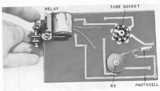
Fig. 616. A light-beam relay which uses a 15-watt lamp for filament dropping
and as a light source.
R1 is a protecting resistor and R2 a 500,000-ohm or 1-meg potentiometer for sensitivity control. V1 is a 6C4 triode, and its filament voltage is obtained by a series circuit with a 15-watt lamp. The latter also serves as a light source. C1 is a 4-8-pf 150-volt electrolytic capacitor which prevents relay chatter. The 15-watt lamp can be set up with suitable optics to give a narrow light beam. When the beam is focused on PC-1, and R2 is adjusted properly, interruption of the light will cause relay action. The spdt relay is wired to give the desired switching action in the outside circuit being controlled.
Circuits using Ampecs
The following group of circuits are built up around a typical commercially available printed-circuit of the ceramic-based type.
They are examples of what can be done with a basic printed circuit such as a three-stage amplifier. In each of the circuits shown, the amplifier was the building block around which the additional components were mounted. Several approaches have been used, mainly to give the builder a feeling for the methods used rather than for the circuitry itself.
---------
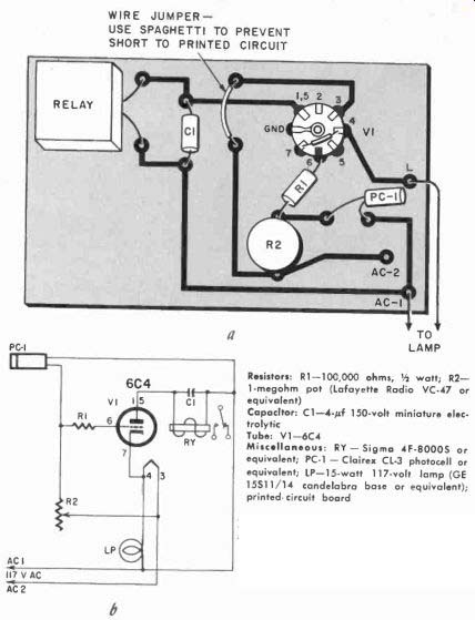
Fig. 617. The printed-circuit layout and schematic for the light-beam relay
shown in Fig. 616.
Resistors: R1-100,000 ohms, 1/2 watt; R2 1-megohm pot (Lafayette Radio VC-47 or equivalent)
Capacitor: C1-4-0 150-volt miniature electrolytic
Tube: V1-6C4
Misc : RY Sigma 4F-8000S or equivalent; PC-1- Clairex CL-3 photocell or equivalent; LP-15.watt 117-volt lamp (GE 15511/14 candelabra base or equivalent); printed circuit board
-----------
The Ampec unit shown in Fig. 618 is a three-stage audio amplifier capable of running 1 millivolt or so input up to two milliwatts output. Output plate loads are in the range of 50,000 to 100,000 ohms and, at 1,000 cycles, the gain of the unit is about 5,000. The capacitors are rated at 150 working volts de and tested at 300 volts. The resistors are nominally rated at 1/5 watt. The entire Ampec is coated with phenolic resin and high-temperature wax.
The conductive paths are pure silver fired to a steatite base. The manufacturer furnishes 26-gauge tinned leads approximately 1 1/2 inches long. The model used in these circuits was a No. PC-201 with a tube complement of one CK525AX and two CK512AX subminiatures. The schematic is shown in Fig. 619.
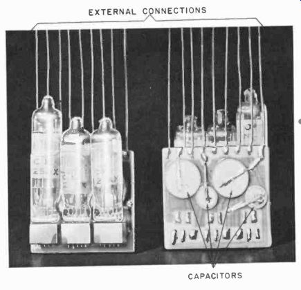
Fig. 618. Several views of the Ampec, a packaged 3-stage amplifier (Courtesy
Centralab Division of Globe- Union. Inc.)
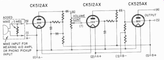
Fig. 619. Schematic of the Ampec. Notice the addition of an external micro
phone.
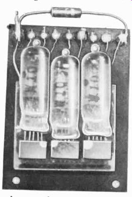
Fig. 620. By connecting a suit able resistor across the input circuit, the
Ampec can be used as the heart of a hearing aid.
Auxiliary components
Suitable external components for the Ampec would be sub miniature volume controls such as the Centralab B16-series, 1/4-watt carbon resistors, ceramic capacitors for low capacitances, and tantalum or metalized paper capacitors for highest capacitances in the 22.5-45-volt range.
Subminiature transformers such as the UTC subouncers can be used for impedance matching. The B-voltage on the Ampec is usually limited to 45, unless otherwise shown.
-----------------
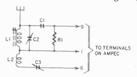
Fig. 621.
This simple circuit converts the packaged amplifier into a grid-detection receiver.
---------
Resistor: R1-5-10 megohms, Y2 watt
Capacitors: C1-5-Anf-.01-µf ceramic; C2 to match L1 for frequency desired; C3-8 50-unf trimmer (Centralab 822AN or equivalent)
Coils: L1-to match C2 for desired frequency (use a slug-tuned form); L2-10 turns No. 22 dcc wire wound over L1
Miscellaneous: hookup wire; mounting hard ware
------------------
Input circuits
The Ampec can be made the basis of a hearing-aid amplifier by tying a 2-5-megohm resistor across the input grid circuit, as shown in Figs. 619 and 620. Another variation is to use a contact microphone or phonograph pickup cartridge as an input device. In these two hookups, the Ampec can be used as either an audio preamp or an industrial or medical stethoscope.
Subminiature radio sets
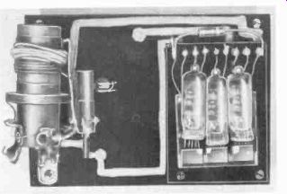
Fig. 622. Another radio receiver built around the Ampec.
In the unit shown in Fig. 621, the Ampec has been built into a grid-detection receiver. C1 is a small ceramic and C3 a tubular glass trimmer. R1 is a 6-megohm, 1/4-watt resistor. The tank components, L1 and C2, are chosen to tune the desired frequency.
With modern components, the L1-C2 package for the broadcast band is smaller than the size of conventional 365-uuf tuning capacitors.
------------
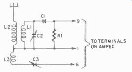
Fig. 623. This circuit is used to convert the Ampec into the unit shown in
Fig. 622.
Resistor: R1-5-10 megohms, 1/2 watt
Capacitors: C1-5-110-.01-0 ceramic; C2-to match 1.1 for frequency desired; C3 8-50-µi.if trimmer (Centrolab 822AN or equivalent) Coils: LI, 12-standard broadcast antenna; L3-10 turns No. 22 dcc wire wound over L1, L2
----------------
Fig. 622 shows an Ampec with a broadcast antenna coil front end; a tickler winding has been added to the coil. The schematic is shown in Fig. 623.
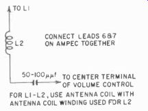
Fig. 624. A simple circuit which converts the receiver of Fig. 623 into a
regenerative type.
The receiver circuits above can be made regenerative by the conversion shown in Fig. 624. Here, L2 is connected to the center tap of the control potentiometer by a 50-p uf capacitor, and the plate and No. 2 grid leads are tied together.
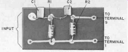
Fig. 625. This simple network is used for the input to a signal tracer.
Signal tracers, integrators, differentiators
Fig. 625 shows an example of a front end for a signal tracer made up for use with the Ampec. Both three-dimensional components and etched circuit techniques are used in the band-pass network that precedes the Ampec itself. Variations of the R-C networks are shown in Fig. 626, where they are used as integrators and differentiators. Their principal advantage is the ease with which they can be plugged into a circuit to change operating values. These R-C networks can be used as the basis of many circuits-frequency bridges of and rf oscillators, and relay timers, to name only a few. Commercial versions of these R-C combinations have been taken up in detail in Section 3; but occasions come up where a commercial unit is not available (for original or replacement purposes) and the technician should know how to build his own. Fig. 627 shows the details of the units In Figs. 625 and 626.
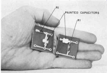
Fig. 626. Variations of the R-C network shown in Fig. 625 are used as integrators
and differentiators.
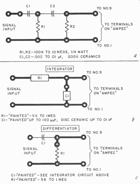
Fig. 627. R-C combinations in printed-circuit form. The unit at the top is
a two-section differentiating circuit.
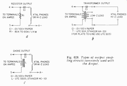
Fig. 628. Types of output coupling circuits commonly used with the Ampec.
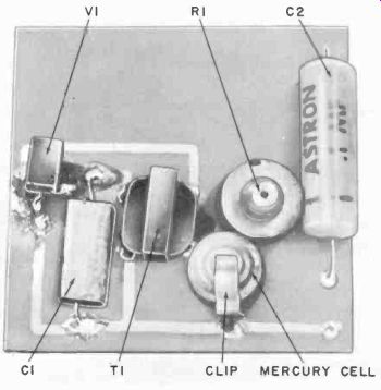
Fig. 629. A transistor audio oscillator which was built wing the copper-laminate
technique.
------------
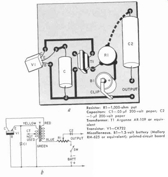
Fig. 630. Schematic and printed-circuit pattern for the audio oscillator shown
in Fig. 629. The center of the potentiometer, R1, is connected to C2 by a conductor
on the underside of the board. The battery is plugged in and out for switch
action.
Resistor: R1-1,000-ohm pot
Capacitors: C1-.05-0 200-volt paper; C2 -1-0 200-volt paper
Transformer: T1 Argonne AR-109 or equivalent
Transistor: V1-CK722
Miscellaneous. 81-1.3-volt battery (Mallory RM-625 or equivalent); printed-circuit board
-------------
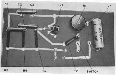
Fig. 631. A phase-shift audio oscillator which uses printed-circuit techniques.
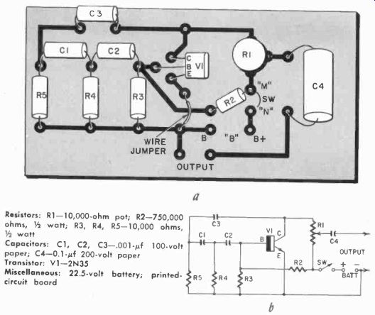
Fig. 632. Printed-circuit board arrangement and circuit diagram of a transistor
audio oscillator. The battery is external to the board and is hooked up to
the terminals at "B". A wire jumper is soldered from the emitter
circuit to the B-minus bus as shown. SW is a piece of tinned hook-up wire soldered
at point "M". Pressing SW into hole "N" completes the circuit.
--------
Resistors: R1-10,000-ohm pot; R2-750,000 ohms, 1/2 watt; R3, R4, R5-10,000 ohms, 1/2 watt
Capacitors: C1, C2, C3-.001-uf 100-volt paper; C4-0.1-µf 200-volt paper
Transistor: V1-2N35 Miscall s. 22.5-volt battery; printed-circuit board
------------
Output circuits for Ampecs
Depending on the output device, the plate of the final tube must be matched to the impedance of the load. Shown in Fig. 628 are the three main types of output coupling used with the Ampec. On the left is the resistor type, which generally gives better results at the lower frequencies, according to the manufacturer; on the right, the transformer output. The remaining output circuit is a choke type.
Bias considerations
There are several models of the Ampec, and the manufacturer's instructions should be followed closely to prevent damage to the unit and also to obtain the best results. In the model 201, the 1,500-ohm resistor (R7, Fig. 619) was designed for use with a 30-volt B supply. If the battery voltage and output coupling arrangements are varied, R7 may have to be shunted for best performance. With models 202 and 203, other minor changes are necessary. Model 202 has a zero-bias output stage, and model 203 uses grid-bias. In addition, model 203 is designed to operate with two CK538DX tubes instead of CK512's, and a CK548DX instead of the CK525.
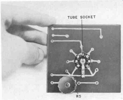
Fig. 633. Printed-circuit board for an oscillator that can be used in radio-control
service.
----------------
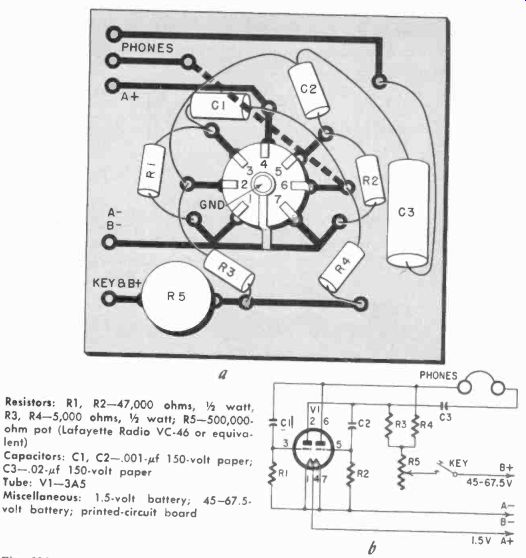
Fig. 634. Printed-circuit board and circuit diagram of a twin-triode oscillator.
Pin 6 has a crossover on the opposite side of the board which goes to the phones.
All component leads should be insulated with spaghetti. The ground lug on the
tube socket is soldered to the A-bus for support. The key and batteries are
external to the board.
-----------
Resistors: R1, R2-47,000 ohms, 1/2 watt, R3, R4-5,000 ohms, 1/2 watt; R5-500,000-ohm pot (Lafayette Radio VC-46 or equivalent)
Capacitors: C1, C2-.001-0 150-volt paper, C3-.02-uf 150-volt paper
Tube: V1-3A5
Miscellaneous: 1 5-volt battery, 45 67 5-volt battery; printed-circuit board
------------------------
Printed-circuit audio oscillators
Fig. 629 shows a printed circuit transistor audio oscillator built up using the copper-laminate etch technique. The pattern is first laid down with an asphaltum resist or other materials mentioned in Section 2. The plate is then etched with ferric chloride or ammonium persulfate, and the resist removed. Then eyelet holes are drilled and eyelets mounted. The schematic ( Fig. 630) resembles the circuit pattern closely and should be used as a guide to the layout and mounting of components.
Another version of a printed-circuit audio oscillator is shown in Fig. 631; resistors and capacitors have been used to make up a phase-shift unit. Fig. 632 shows the pictorial and schematic. An etched laminate-base technique was used, but the three 10,000-ohm and 750,000-ohm resistors were painted on, using carbon-base paints ( Section 2 ). The resistors should be allowed to age for several days and then checked with an ohmmeter. By scraping or altering the physical dimensions of the painted resistors the builder can come very close to the values given. The values in the schematic should produce a tone between 1,000 and 4,000 cycles.
High-impedance phones or high-impedance output transformer coupling will give the best results.
The 750,000-ohm resistor and R3 form a voltage-divider network which stabilizes the bias on the base connection of the 2N35 transistor. Oscillator frequency can be varied by changing C1, C2 and C3 equally. Decreasing the capacitance will raise the frequency.
Tube circuits
A 3A5 high-frequency twin-triode has been used as the heart of the printed-circuit oscillator shown in Fig. 633. Etched-circuit construction has been used, and the schematic of Fig. 634 is a guide to the physical layout. The same circuit can be built up with the coil painted on the envelope of the tube ( cf ."lipstick" transmitter, Section 7) the circuit shown here is basically a push pull oscillator and can be adapted for 6-meter radio control work by licensed hams.
Slightly more compact is the printed-circuit board for the Pierce crystal oscillator ( Fig. 635 ). This is built around a CK507AX subminiature hearing-aid tube. Etched technique was used. The circuit, known as the CGQ in Navy circles during World War II, packs a good wallop in spite of its tiny size. A pictorial assembly is shown in Fig. 636.
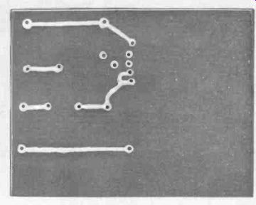
Fig. 635. Printed-circuit board for a Pierce crystal oscillator.
High-frequency crystal-controlled transmitter A printed-circuit version of a crystal-controlled transmitter is shown in Fig. 637. The circuit values are for operation in the 27.255- mhz or Citizens radio control band. The advantages of printed-circuit construction can be seen in the "flat" look of the unit; the entire assembly can be incorporated into a hand held type of transmitter with battery supply. Silver paint was used to lay down most of the conductors, and wire was used at the tube socket to allow for right-angle tube mounting. Fig. 638 shows the construction details.
--------------------
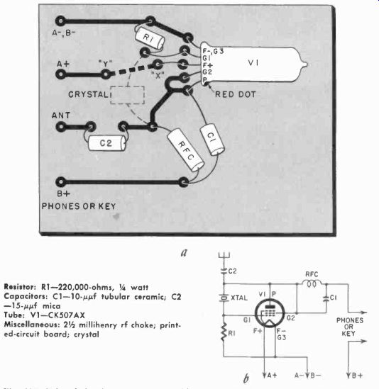
Fig. 636. Printed-circuit pattern (front side) and schematic for the crystal
oscillator shown in Fig. 635. The crystal is mounted on the opposite side of
the board. The filament plus lead goes under the board at "X" and
comes back up at "Y". "X" to "Y" is etched or
painted on rear side. The crystal holder should be insulated from this "X" to "Y" length
of conductor.
Resistor: R1-220,000-ohms, 1/4 watt
Capacitors: C1-10-uuf tubular ceramic; C2-15-uuf mica
Tube: V1-CK507AX
Miscellaneous: 2 1/2 millihenry rf choke; printed-circuit board; crystal
---------------------
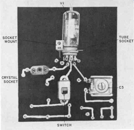
Fig. 637. A printed-circuit board was used in the construction of this 27.255-
mhz transmitter.
Phonograph pickup
The phono pickup shown in Fig. 639 is constructed from a piece of 1/16-inch plexiglas. Two "ears" are cut out, and a carbon paint line is run from ear to ear along the Plexiglas. A piece of Plexiglas rod is drilled and tapped for a phono needle at the end opposite the ears. The entire assembly is put in series with a 1.5 volt battery and potentiometer, and fed into the front end of an amplifier (Fig. 640). The builder will have to experiment with the paint thickness, width and resistance, depending on the amplifier circuit used.
The beam flexes as it rides in the record grooves and causes resistance variations of the printed paths on the beam. These changes modulate the series voltage to the input of the amplifier and are reproduced as sound.
While the unit will not satisfy the critical ear of the high-fidelity hound, it is another interesting example of what can be done with printed-circuit techniques.
Printed-circuit switches
Printed circuitry can be used to simplify switch construction.
One interesting aspect of switches using printed-circuit designs is that the cost of the switch is fairly independent of its complexity in commercial production quantities. Thus, a 30-pole selector switch could be produced about as cheaply as a 4-pole unit, since the major costs are the master drawing and photographic work. Machining costs of conventional electromechanical switches are several times those of etched-laminate switches.
Copper laminates are too soft to be used commercially without further alterations-copper has a relatively short wearing life. In many cases, the copper pattern is silver-or nickel-plated. The hardest and longest wearing surfaces are produced by combi nations of nickel and rhodium plating techniques.
----------------
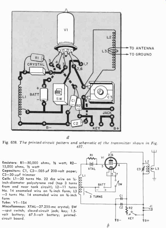
Fig. 638. The printed-circuit pattern and schematic of the transmitter shown
in Fig. 637.
Resistors: R1-50,000 ohms, watt; R2 15,000 ohms, V2 watt
Capacitors: C1, C2-.005-0 200-volt paper; C3-30-uuf trimmer
Coils: L1-30 turns No. 22 dcc wire on 0.25 inch-diameter polystyrene rod (tap 3 turns from end near tank circuit); L2-11 turns No. 14 enameled wire on 3/4-inch form; L3-5 turns No. 14 enameled wire on 3/4-inch form
Tube: V1-154
Miscellaneous: XTAL-27.255- mhz crystal; SW-spst switch; closed-circuit jack; key; 1.5-volt battery; 67.5-volt battery; printed-circuit board.
----------------
One problem inherent in silver plating or the use of silver-laminate combinations is that of silver "migration." The silver particles tend to travel into the nonconducting part of the laminate base and cause short-circuiting under certain conditions such as high humidity or fast operation at high voltage. The amount of "migration" seems to increase with higher applied de voltages and also with relative humidity increases.
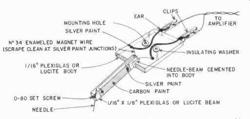
Fig. 639. Scrap plastic and printed-circuit paints are used to construct this
simple phono pickup.
----------------
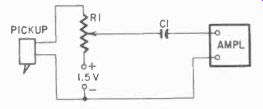
Fig. 640. Circuit of the printed-circuit phono pickup.
Resistor: R1-1-megohm pot
Capacitor: C1-.002-0 200-volt paper
Misc. all scrap Lucite or Plexiglas; wire; silver paint; 1.5-volt battery
-------------------
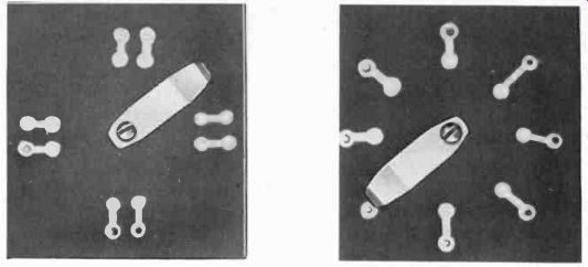
Fig. 642. In this switch the rotary member is independent of the con trolled
circuits.
Fig. 643. The rotating component of this printed-circuit switch forms the common return.
Raised and flush switch patterns
The factors to keep in mind when designing printed-circuit switches are speed of operation, life in terms of number of operations before failure, surrounding conditions such as temperature and humidity, and the torque (turning force) required to actuate the switch.
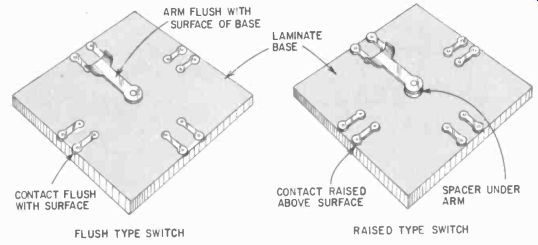
Fig. 641. Printed-circuit switches can be of the raised or flush type.
Either raised or flush contacts can be used in printed-circuit switch construction ( Fig. 641). The raised type is suited for low-speed or hand-switching. Raised designs in copper with silver plate have a life of up to 500,000 or so operations. On the other hand, flush designs with rhodium plating can give life expectancies of 10,000,000 operations or more. Raised patterns also have the additional disadvantage of bumpy operation and require more turning force to operate.
Because of the low arc resistance of phenolic laminates, epoxy glass is used for switches where arcing is a factor. Brush materials in commercial use include phosphor bronze, beryllium copper, gold alloys and special combinations of silver with graphite. Some manufacturers claim that certain lubricating compounds increase switch life.
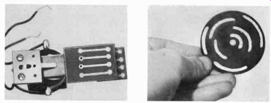
Fig. 644. This hinged relay switch activates four separate circuit simultaneously.
Fig. 645. A rotating switch wheel of this type can be used as the heart of
various timing devices.
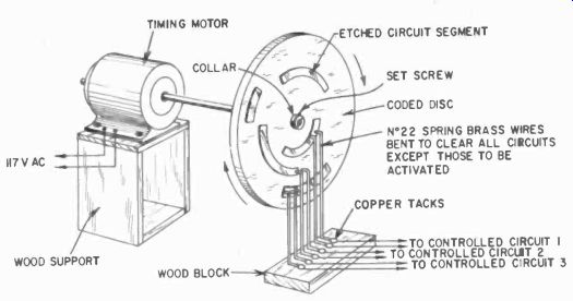
Fig. 646. Rotary printed-circuit switch can be used for timing operations.
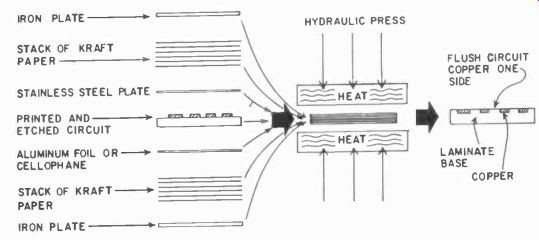
Fig.
647. The steps involved in the fabrication of the flush type of printed circuit.
(Courtesy Continental Diamond Fibre Co.)
Making printed-circuit switches
The raised-contact switches described are made with the etched copper-laminate technique. The experimenter can have these plated or else plate them himself. However, since the average amateur usually needs only switches with low life expectancy, plating is generally not required.
The raised-contact switch is the easiest to produce as far as the experimenter is concerned; designs are limited only by his ingenuity.
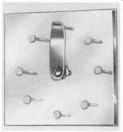
Fig. 648. This switch was made from a plastic plate and copper tacks.
Fig. 642 is a rotary switch in which the circuits are completed independently of the rotating member; Fig. 643 has a common return through the rotating member. Fig. 644 is a hinged relay switch in which four separate circuits are closed simultaneously by a set of printed-circuit plates.
Fig. 645 is a rotary switch wheel for timing purposes. The wheel can be driven by a motor (Fig. 646), different contacts being used to turn appliances and other devices on and off at various intervals.
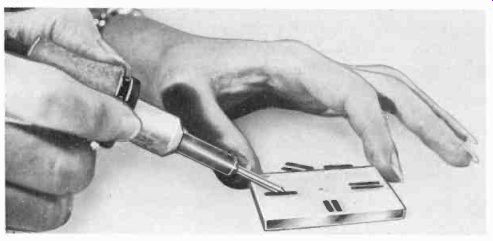
Fig. 649. Copper strips are imbedded in a plastic base to make this switch.
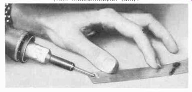
Fig. 650. Technique used for stripping the insulation from multiconductor
cable.
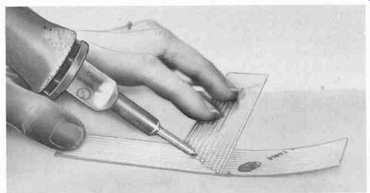
Fig. 651. Splices can be made in flat cable. However, always be sure to insulate
the wires from each other.
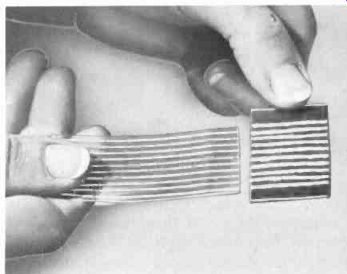
Fig. 652. A home-made male connector etched from laminate stock.
Flush circuit design
One of the industrial techniques for making flush-contact printed-circuit switches is shown in Fig. 647. A sandwich of paper and metal is built up and placed in a hydraulic press under heat and pressure to produce either a one-sided or two-sided flush printed circuit.
The experimenter can make his own flush switches in several ways by using polystyrene or one of the methacrylate plastics as a base material. Fig. 648 shows a switch made by drilling holes in a polystyrene plate, inserting copper flat-head tacks, and then pressing the tack heads down flush with the top of the plastic plate. The pressing operation can be done with a chisel-tip 60-watt soldering iron or a domestic clothes iron. If the clothes iron is used, a sheet of shim brass should be laid over the entire top of the plastic plate. The iron is removed as soon as the heads "feel" flush with the plate surface. After the tacks are heated to the flush position, the top of the plastic sheet is polished with fine sandpaper and pumice. A higher polish can he obtained with rottenstone or jeweler's rouge. All abrasives should be washed off the plastic with a detergent and a warm-water rinse.
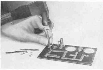
Fig. 653. Stamped-wiring techniques can he duplicated with copper foil riveted
to insulating stock.
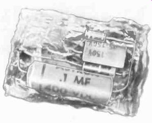
Fig. 654. Preliminary steps in potting a simple R-C circuit.
A second design is shown in Fig. 649. This is made by pressing rectangular strips of brass into the plate at 90° positions, one pair of strips at each quarter-turn. The imbedded strips are then drilled and polished. The wiper is designed to short each pair of strips, but its width must be less than the distance between adjacent pairs of strips, to prevent shorting between positions.
Each of the switches shown can be silver-plated without electricity by rubbing with a silver-chloride paste. One commercial plating powder is Cool-Amps.
Printed-circuit cables
Fig. 650 shows how to strip the plastic from a multiconductor flat-tape type cable: use a pencil type iron, and apply heat sparingly to melt the plastic around each conductor.
Splices in flat cable can be made as shown in Fig. 651. The splice should be taped with plastic electrical tape such as Scotch tape No. 33.
Fig. 652 shows a home-made male connector for use with flat printed-circuit cable. The connector was etched from laminate stock.
Stamped wiring
Stamped wiring (described in Section 2) can be duplicated on a small scale by cutting 28-30-gauge copper foil into strips 1/8 to 1/4-inch wide and as long as required for the circuit being laid out. The foil is then drilled with a No. 50 or 53 drill, and brass eyelets riveted in as shown in Fig. 653.
The foil can be obtained from hobby or craft stores where it is normally sold for tapping out or embossing copper pictures.
Fig. 655. The potting compound is poured around the component until it is covered.
Potting
"Potting" is a technique for casting components or component assemblies in building blocks so that they can be handled as separate units. The varieties of potting compounds available commercially are too numerous to mention.
A typical working method for the experimenter is as follows:
1. Set up the part or parts to be potted in a box made from house hold aluminum foil or cardboard. Apply silicone grease ( Amphenol No. 307) or Vaseline to the box to help strip the box away from the components after the potting compound hardens. Fig. 654 shows the setup for an R-C network.
2. Obtain a pint of No. 17 Castiplast resin and 4 oz of No. 1 hardener catalyst ( National Engineering Products, Washington Bldg., Washington, D. C. ). Mix 12 teaspoons of the Castiplast with 1 teaspoon of the hardener. Stir thoroughly, but slowly, to avoid formation of too many air bubbles.
3. Pour the mixture around the component setup, as shown in Fig. 655, and allow to harden according to the manufacturer's instructions. In this case, the time is 24 hours at room temperature. The useful "pouring life" of the mixture is about 30 minutes. After this, it becomes too thick to pour, so work accordingly.
Fig. 655. The potting compound
is poured around the component until it is covered.Fig. 656. After the potting job is completed, the component is protected from
external heat and moisture.
A finished job is shown in Fig. 656. Coils and inductive components should not be potted unless special grades of potting compounds are used, since potting usually affects the Q in rf circuits.
Consult the potting-compound manufacturers before attempting such units.