AMAZON multi-meters discounts AMAZON oscilloscope discounts
COMMERCIALLY AVAILABLE high-frequency transistors extend the operating range of tubeless equipment into the radio-frequency spectrum. Transistorized radio-frequency and intermediate-frequency amplifiers now are entirely practical for applications in receivers, instruments and control devices.
The low dc power requirements of transistorized high-frequency amplifiers, as in other transistorized circuits, suit them to economical battery operation. This is invaluable when such amplifiers are to be used in conjunction with other equipment but must not draw power from the equipment.
Broadcast-band rf amplifier and preselector Fig. 201 shows the circuit of a tuned radio-frequency amplifier suitable for use as a preselector ahead of a broadcast receiver to increase the selectivity of the latter.
Employing a Sylvania 2N94A n-p-n-type rf transistor, this amplifier may be tuned continuously from 500 to 1,700 khz and provides a power gain of 20 db, or 100 times. Input and output impedances are approximately 500 ohms. Maximum input-signal voltage is 300 millivolts. In the middle of the standard broadcast band (1,000 khz) the amplifier bandwidth is 20 khz at the 3-db points (70.7% of voltage at peak of response curve).
The coils are wound with No. 32 enameled wire on 1-inch-diameter forms according to the instructions given in Table 2. Each primary and secondary coil set (L1-L2 and L3-L4) must be en closed in a grounded metal shield can to prevent oscillation.
While the two sections (C1 and C2) of the tuning capacitor are ganged together for simultaneous adjustment, the rotors cannot be connected together electrically. This prohibits use of the standard two-gang unit. It is best to gang together two separate 365-14 variable capacitors by an insulated shaft coupling or belt drive and to insulate the entire assembly from the metal chassis. An insulating shaft coupling also must be provided between the capacitor and tuning dial to prevent detuning effects due to body capacitance.
Total current drain of the amplifier is approximately 10 milli amperes dc from the 6-volt battery.
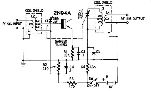
Fig. 201. Broadcast-band rf amplifier and pre selector.

Table 2-Coil Table for RF Amplifier L1-10 turns No. 32 enameled wire closewound
around "ground end" of L2 and insulated from it.
L2-130 turns No. 32 enameled wire closewound on 1-inch-diameter form. Tap 15th turn from "ground" end.
L3-130 turns No. 32 enameled wire closewound on 1-inch-diameter form. Tap 80th turn from "ground" end.
L4-12 turns No. 32 enameled wire closewound around the ground end of L3 and insulated from it.
Single-stage, single-tuned 455- khz if amplifier
A simple 455- khz intermediate-frequency amplifier circuit suitable for inclusion in a small radio receiver or for general-purpose experimental applications is shown in Fig. 202. Employing a Raytheon 2N112/CK760 rf transistor, this amplifier provides a power gain of 30 db. Bandpass is 10 khz at the 6 db points.
Input and output impedances of the amplifier both are 600 ohms.
These values are convenient for operation of the unit between a low- impedance converter, such as a crystal diode, and a succeeding transistor if amplifier or second detector stage or crystal-diode second detector.
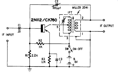
Fig. 202. Single-tuned one-stage 455- khz if amplifier.
Because of the inherent regenerative nature of the common-emitter circuit, oscillation will occur unless this circuit is neutralized.
Variable capacitor C2 is provided for this purpose. The circuit is neutralized when C2 is set approximately to 80 uuF, but the capacitance setting will depend upon the actual transistor internal capacitances and upon the stray circuit capacitances due to the layout.
The miniature, transistor type if transformer has an input (collector) impedance of 25,000 ohms and an output impedance of 600 ohms. The figures shown on the transformer leads correspond to the manufacturer's coding and must be followed in the wiring to obtain correct amplification and neutralization.
Total current drain from the 6-volt battery is approximately 1.5 milliamperes dc.
The amplifier is aligned initially in the conventional manner:
(1) Connect an amplitude-modulated signal generator to the IF INPUT terminals. (2) Connect a detector (ac vacuum-tube volt meter or high-impedance magnetic headphones in series with a 1N34 germanium diode) to the IF OUTPUT terminals. (3) Close switch SW. (4) Set the signal generator to 455 khz. (5) Time the slug of the if transformer for maximum signal in the detector. Reduce the output of the signal generator if the amplifier or detector blocks.
Two-stage 455- khz if amplifier In a majority of applications, the single-stage if amplifier de scribed in the preceding section will not provide sufficient gain. A 60-db power gain may be obtained with the two-stage if amplifier circuit shown in Fig. 203. Sensitive receiver and instrument demands may be met with this amount of amplification.
This amplifier also employs Raytheon 2N112/CK760 rf transistors and transistor type miniature if transformers, as in the preceding example. Total current drain from the 6-volt battery is approximately 7 milliamperes dc.
The input impedance of the amplifier is 25,000 ohms; output impedance 600 ohms. These values are satisfactory for working out of a transistorized converter stage and into either a diode or transistor type second detector. The circuit is neutralized automatically by the fixed capacitors C1 and C2.
The figures on the leads of the if transformers in Fig. 203 correspond to the manufacturer's coding and must be followed for correct amplification and neutralization.
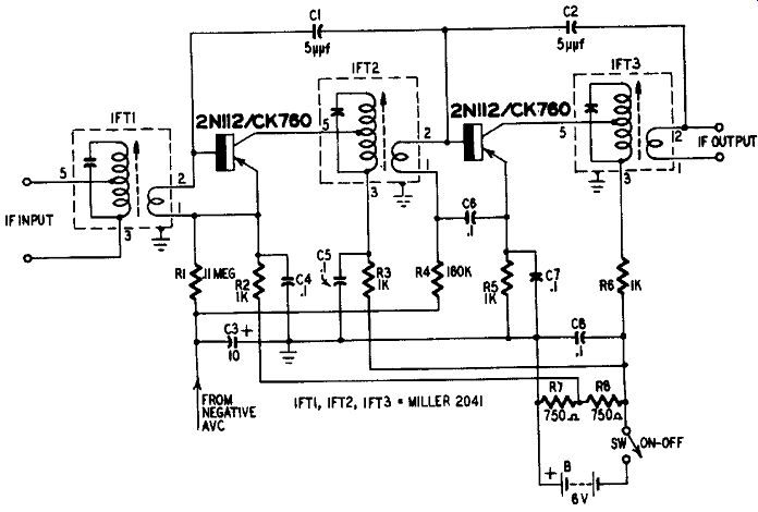
Fig. 203. Two-stage 455- khz if amplifier.
Negative avc voltage, derived from the second detector when the if amplifier is included in a superheterodyne receiver, is applied to the if transistors at the lower ends of resistors R1 and R4. If avc voltage is not available, connect R1 and R4 to the negative 6-volt line (e.g., to the right-hand end of resistor R8) .
The amplifier is aligned to 455 khz initially in the conventional manner, as described in the preceding section, with an AM signal generator connected to the IF INPUT terminals and a detector to the IF OUTPUT terminals. The slugs of the transformers (T1, T2 and T3) are tuned for peak output signal. It is necessary to jockey back and forth between these adjustments until all three transformers are "peaked." 50- khz if amplifier Low-frequency if amplifiers are employed in heterodyne type instruments and as selectivity boosters for CW receivers. It is advantageous to transistorize such amplifiers when battery operation, especially in portable service, is desired.
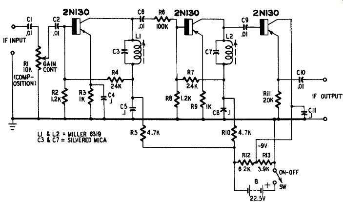
Fig. 204. 50- khz if amplifier.
Fig. 204 shows the circuit of a 50- khz peaked amplifier employing three Raytheon 2N130 transistors. Parallel-resonant collector tuning is employed, since 50- khz if transformers with the proper impedance ratings for interstage coupling between transistors are not available at this writing. For this purpose, slug-tuned inductors L1 and L2 (variable from 15 to 60 mh) are connected in parallel with silvered mica capacitors C3 and C7, respectively.
The first two stages are common-emitter amplifiers. The emitter current-limiting resistor R9 in the second stage is left unbypassed.
The resulting degeneration raises the input impedance of this stage and this feature, plus the effect of the series input resistor (R6) , reduces the second-stage loading on the first-stage tuned circuit (L1-C3) , thereby preserving the selectivity of the latter. The output stage is a common-collector amplifier which offers a high impedance and minimum detuning to the second-stage tuned circuit (L2-C7) and provides comparatively low impedance output. This arrangement protects the second-stage tuned circuit from fluctuating external load conditions.
At the 50- khz peak, the overall voltage gain of this amplifier is 500.
With GAIN CONTROL R1 set to maximum, the maximum recommended input-signal voltage is 10 millivolts rms. The corresponding maximum output-signal voltage is 5 volts rms. Fig. 205 shows the frequency response.
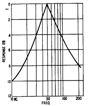
Fig. 205. Frequency response of the circuit shown in Fig. 204.
Input impedance is approximately 1,000 ohms and output impedance 20,000 ohms. Total current drain is approximately 8 milliamperes dc from the 22.5-volt battery.
The 50- khz if amplifier is aligned with the aid of an amplitude-modulated signal generator: (1) Connect the generator output to the IF INPUT terminals. (2) Connect a detector (ac vacuum-tube voltmeter or high-impedance magnetic headphones in parallel with a 1N34 germanium diode) to the IF OUTPUT terminals. (3) Set GAIN CONTROL R1 to midrange. (4) Switch on the signal generator and if amplifier. (5) Tune the slugs in inductors L1 and L2 for peak output signal, working back and forth between the two adjustments until both stages are peaked. Reduce the generator signal or the amplifier GAIN CONTROL (R1) setting if the amplifier or detector blocks from excessive signal strength.
Transistors for high-frequency rf amplifiers
Radio-frequency amplifiers for operation at frequencies above the standard broadcast band may be constructed, employing essentially the same design as that given in Fig. 201. However, the values of L1 , L2, L3, L4, C1 and C2 must be chosen for resonance at the desired operating frequencies and an rf transistor having the proper operating-frequency range employed. A variety of high-frequency transistors is available commercially.
Table 3 shows the alpha cutoff frequency of common rf transistors.
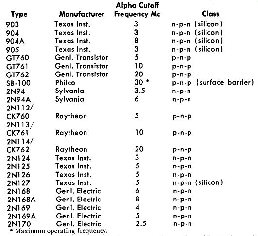
Table 3- Rf Transistors
Maximum operating frequency.
The maximum operating frequency shown in table 3 above is 30 mhz. At the time of this writing, this is the highest frequency rating of commercially available triode-type transistors but this is not to be construed as the ultimate frequency of transistor operation.
The thinner the base layer, the higher the maximum operating frequency of a junction transistor. In recent developmental transistors produced in the laboratory, base layers only 50 millionths of an inch thick have been formed in transistors having cutoff frequencies between 500 and 600 mhz (Bell Telephone Laboratories). But at the time of this writing no predictions have been made as to when these uhf transistors will be available to the experimenter and hobbyist. It may be reasonably expected, however, that new fabrication techniques which make possible the production of microscopic layers in a tiny semiconductor bar will bring uhf junction transistors within the reach of all users within the next few years.
Another significant development, still in the pilot production stage at this writing, is the high-frequency tetrode transistor. One such n-p-n unit (General Electric) has a cutoff frequency of 120 mhz and a collector dissipation rating of 50 milliwatts.
With transistors now commercially available with frequency ratings up to 30 mhz, and with power transistors available for the audio frequencies, uhf transistors are all that is required to complete the applications picture in receivers and test instruments other than the microwave type.
Uhf transistors with reasonable power dissipation ratings Will make possible transistorized portable transceivers (especially "handie-talkies"), compact transmitters and receivers for garage-door opening and similar control purposes, and uhf signal generators and "grid"-dip oscillators. Conventional, low-powered, uhf transistors will be invaluable in TV front ends and high-frequency video amplifiers, and in some radar and altimeter applications.