AMAZON multi-meters discounts
AMAZON oscilloscope discounts
IN radio receivers, transistors have been a boon to miniaturization, I making possible for the first time, for example, a practical super heterodyne receiver small enough to fit into a coat pocket. In large receivers, as well as in small ones, the low current requirements of transistors have made battery operation both economical and feasible. Less expensive batteries and long battery life characterize transistor radios as contrasted to tube-type portable sets.
The chief interest of many experimenters with transistors is building and operating receivers. To pick up broadcasts at loud speaker volume with a miniature set containing only filament-less crystal devices has a constant exhilaration.
During the early years of the transistor, engineers and experimenters alike tested the transistor in all types of receivers. Substantial progress was delayed until high-frequency commercial transistors and suitable miniature if and class-B of transformers to match transistor impedances appeared on the market. The first factory built transistorized superhet receiver was placed on sale during the transistor's sixth year of existence. A commercial shortwave converter did not appear until its eighth year.
This section gives the practical details of a number of receiver circuits. A cross-section has been made of the supply of good circuits calculated to fill the need of experimenters, hobbyists, and others.
Single-transistor broadcast receiver
When high sensitivity is not required, as in picking up strong local stations, a simple one-transistor receiver circuit will give good headphone operation. For maximum performance, an rf transistor is recommended.
3V ON-OFF
= 25 TURNS NO. 32 ENAMELED WIRE CLOSEWOUND OVER GROUND END OF LZ.
L2= 144 TURNS NO. 32 ENAMELED WIRE CUBEAOUND CM 1" DIAMETER FORM. TAP BOTH TURN FROM GROUND ENO.
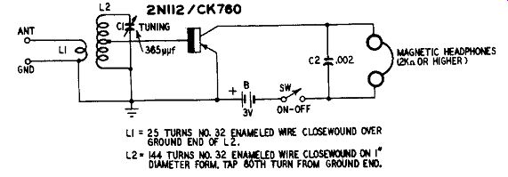
Fig. 601. Single-transistor broad cast receiver.
Fig. 601 shows a single-transistor receiver circuit employing a Raytheon 2N112/CK760 transistor and 3-volt battery. The base connection for the transistor is tapped down the secondary coil L2 of the rf input transformer for impedance matching and improved selectivity. The collector output circuit feeds the headphones directly. Because the headphones are connected in series with battery B and the collector electrode, only the magnetic type may be used.
Since crystal headphones block the passage of dc, they are unsatisfactory for use in this circuit.
The rf input transformer consists of a 144-turn tapped secondary winding and a 25-turn primary. The coils are wound on a 1-inch diameter plastic or fiber tube 1.5 inches long. Begin the construction by closewinding 144 turns of No. 32 enameled wire on the tube.
Tap the 80th turn from the end of the coil to be grounded. This completes the secondary L2. Next, wind one turn of 3A-inch (width) Scotch tape tightly around the ground end of the secondary coil. This provides insulation for the primary winding. Finally, close-wind 25 turns of No. 32 enameled wire on top of the tape in the same direction as the secondary coil. This completes winding L1.
The single-section 365-uuf variable capacitor C1 provides tuning throughout the standard broadcast band. When the receiver is to be made very compact, a miniature flat-type tuning capacitor, such as Lafayette MS-215 or MS-274, may be used.
The receiver gives best results with a good outside antenna and earth ground. However, it will operate with various emergency antennas, either indoor or outdoor types (with or without a ground connection) but the headphone volume will depend directly upon the nearness and power of the station received.
The transistor detector is superior to a diode alone since the transistor provides amplification as well as detection of the signal. The low drain of 4 ua permits use of the smallest-size penlight cells.
Two-transistor broadcast receiver In the receiver circuit shown in Fig. 602, a single-stage transformer-coupled of amplifier employing an inexpensive p-n-p transistor (Raytheon CK722) has been added to the simple detector circuit of Fig. 601. The tuner (L1-L2--C1) has the same specifications as in Fig. 601.
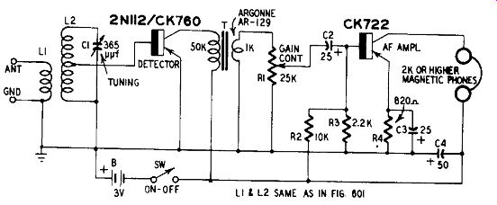
Fig. 602. Two-transistor broadcast receiver.
This receiver gives loud headphone signals when tuned to strong local broadcast stations. Because of the increased gain provided by the audio amplifier, performance with poor antennas is better than when using the one-transistor receiver.
An audio gain control R1 is included since the headphone volume can be excessive on strong nearby stations. Dc base-bias stabilization is provided by the voltage-divider network R2-R3 and the bypassed emitter resistor R4.
The total dc drain from the 3-volt battery is approximately 1 ma.
Miniaturization of simple broadcast tuners
A vest pocket receiver requires a tuner (rf input transformer and tuning capacitor) smaller in size than the L1-L2-C1 combination shown in Figs. 601 and 602.
A miniature unit may be constructed, as shown in Fig. 603, by substituting a ferrite-tuned antenna coil (L) for the original L1 L2 transformer and a flat-type miniature 365-Rtf variable capacitor C, such as Lafayette MS-215 or MS-274, for the standard-size vari able. The rest of the receiver circuit remains the same as in Fig. 601 or 602.
The tuning slug of the coil may be set for full coverage of the broadcast band with the antenna in use. While this tuner arrangement is not as selective as those shown in Figs. 601 and 602, due to poor impedance match to the transistor and absence of the primary ...
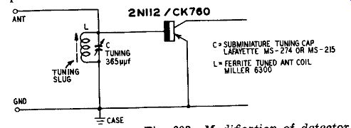
Fig. 603. Modification of detector for miniaturization.
... coil, it permits considerable size reduction and fair performance.
The length of the antenna will affect the tuning range provided by capacitor C, but this can be compensated in most instances by a readjustment of the screw-tuned slug of coil L.
Regenerative broadcast receiver
Fig. 604 shows the circuit of a simple single-circuit regenerative broadcast receiver employing a p-n-p rf transistor (Raytheon 2N 112/CK760) . The sensitivity of this detector circuit is increased by the rf amplifying properties of the regeneration.
A tickler-type feedback circuit is used, output energy being fed back by the tickler coil L2 to the input tuned circuit L1-C2 by inductive coupling. Adjustment of rheostat R controls the amount of regeneration.
Fig. 604-a,-b. Regenerative broadcast receiver.
The tuner coil assembly L1-L2 is wound on a 1-inch diameter plastic or fiber tube, 1.5 inches long. The input coil L1 is wound on the tube first and consists of 144 closewound turns of No. 32 enameled wire. Then a single turn of s/4-inch-wide Scotch tape is wound tightly around one end of the finished coil for insulation of the tickler. The tickler coil L2 next is wound on top of the tape in the same direction as L1. It consists of 40 closewound turns of No. 32 enameled wire.
For the feedback to be of the proper polarity for regeneration, the coils must be phased correctly. Fig. 604-b shows the top of winding L1 labeled B and the top of L2 labeled A. These ends of the coils are connected in the circuit to the headphones and C4 and to the C1-L1-C2-C3 junction, respectively, as shown in Fig. 604-a.
As in a tube-type regenerative detector, the regeneration level should be adjusted to the highest point short of oscillation. The receiver has maximum sensitivity to weak signals in this condition but slightly beyond this point the circuit will break into annoying oscillation.
Fig. 605. Step-tuned diode-transistor broadcast receiver.
Step-tuned diode-transistor broadcast receiver
When only a few stations are located in the service area of a receiver, continuously variable tuning is not needed. Instead, it is convenient for the receiver circuit to be pre-tuned to the various station frequencies and the operator then can select these stations at will by means of a switch or pushbuttons.
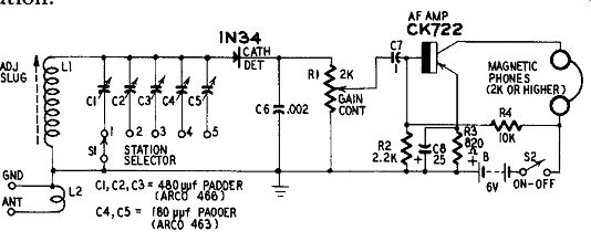
Fig. 605 shows a simple step-type circuit employing a diode detector (1N34)
and transistor audio amplifier (Raytheon CK722) .
The input rf transformer (L1-L2) is pre-tuned to five carrier frequencies by trimmer capacitors C1, C2, C3, C4 and C5, respectively.
Tuning to either desired station then is accomplished by setting switch Si to connect the corresponding trimmer capacitor across coil L1. The reader may provide as many trimmer capacitors as needed for the number of stations to be tuned in, as long as the selector switch (Si) has sufficient positions.
The rf transformer consists of a ferrite-tuned antenna coil L1 (Miller 6300) around the lower end of which are wound five turns of No. 24 dcc wire (L2). Trimmer capacitors C1, C2, and C3 are used for frequencies lower than 1,000 khz and each is a 480-wf screw-adjusted padder (Arco 466) . Trimmers C4 and C5 are for frequencies higher than 1,000 khz and each is 180 [t[Af (Arco 463) . This switched-tuner diode detector is based upon an earlier design by the author. 1 The receiver may be adjusted and aligned initially from received stations or with the aid of an amplitude-modulated signal generator.
The signal is applied to the ANTENNA and GROUND terminals, switch S1 set to position 1 and the lowest-frequency signal tuned in by adjusting C1 and the slug of L1. Next, switch S1 is set to position 5 and the highest-frequency signal tuned in by adjusting trimmer C5.
If this frequency cannot be reached, readjust the slug of L1, then return switch S1 to position 1 and readjust C1 . The intermediate frequencies then may be tuned in successively with switch S1 at its corresponding settings and by adjusting the corresponding trimmer capacitors. However, do not disturb the L1 slug adjustment once the initial point 1 and 5 alignments have been completed.
Push-pull transistor broadcast receiver
Fig. 606 shows the circuit of a push-pull transistor detector circuit based upon a similar diode detector circuit developed earlier by the author. 2 This detector has increased sensitivity and output over the single-ended type and provides a single-stage broadcast receiver for efficient operation of headphones.
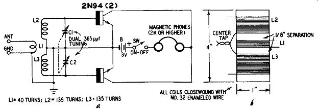
Fig. 606-a,-b. Push- pull transistor broadcast receiver.
Employing two rf transistors ( Sylvania 2N94), this circuit has split-tuned input. The two halves of the secondary winding (L2 L3) of the input transformer are tuned by the two-section 365-mif variable capacitor C1-C2. The primary winding L1 is wound between the halves of the secondary. Fig. 606-b gives the constructional details of this transformer.
This receiver circuit is of special interest when two transistors are available but the components for an audio amplifier stage either are not available or cannot be accommodated in the layout.
Loop-operated diode-transistor broadcast receiver
Although a diode detector is employed in the receiver circuit shown in Fig. 607, this set has high sensitivity due to the gain of the audio amplifier following the diode. It is high enough to permit use of a ferrite rod-type self-contained loop antenna and the audio output is sufficient to operate a loudspeaker. This arrangement makes an excellent, small-sized, portable receiver for local reception.
The circuit employs a diode detector (Raytheon CK705) , high-alpha transistors (Raytheon CK721) in the of amplifier and driver stages and medium-alpha transistors (Raytheon CK722) in the push-pull class-B audio output stage. The audio power output is 110 milliwatts. Four size-D flashlight cells connected in series will supply the direct-current drain for more than 1 month of all-day operation.
The transistor-type ferrite-rod antenna (L) has a very high Q and is provided with a tap for matching the relatively low impedance of the CK705 diode. These features boost the sensitivity and selectivity of the detector circuit. The recommended Miller No. 2000 antenna is a long unit (approximately 9 inches) . Shorter rods
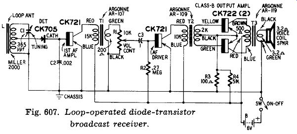
Fig. 607. Loop-operated diode-transistor broadcast receiver.
will not provide sufficient signal pickup. The antenna must be mounted horizontally and clear of metallic objects. The receiver therefore cannot be housed in a metal case, although it can be built on a metal chassis. The antenna is directional in operation, giving best pickup when it is rotated broadside to the station.
The transformers must be connected correctly according to the color coding indicated in Fig. 607. If this is not done, oscillation might occur as a result of feedback due to magnetic coupling between their cores. To minimize coupling, the transformers (when they must be mounted closely together in a compact layout) should be oriented so that their cores are at right angles.
Sun-powered broadcast receiver
The availability of low-powered high-output photocells opens new possibilities for operating radio receivers from sunlight.
The technical literature, as well as daily news releases, already have described full-fledged portable, loudspeaker-operating sets which are powered by sun-battery type photocells. However, the special silicon sun batteries required for this amount of power are priced out of the average experimenter's reach.
Fig. 608 shows the circuit of a simple headphone-type broadcast receiver which can be powered by five inexpensive, miniature, selenium photocells (International Rectifier Corp. B2M) connected in series. This circuit includes a diode detector (Raytheon CK705) and one-stage transistor audio amplifier (Raytheon CK721) . In strong sunlight, robust headphone operation is secured from strong local broadcast stations. Somewhat weaker response is obtained with artificial illumination.
Aside from using a photocell battery as a dc supply, the circuit is entirely conventional. The tuner consists of a small, ferrite-rod antenna coil L (Lafayette MS-166) and the 365-uuf variable capacitor C2. Strong nearby broadcast stations will be picked up directly by coil L, but some additional antenna (and usually a ground also) will be needed to receive the weak ones.
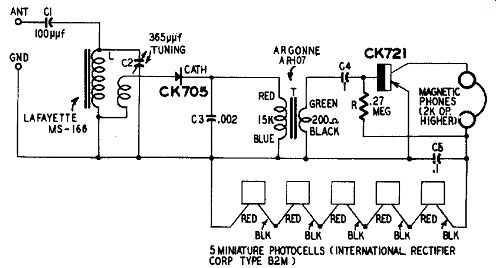
Fig. 608. Sun-powered broadcast receiver.
The builder must be careful to follow the color coding of the photocell leads, as shown in Fig. 608, otherwise series-circuit multiplication of the photocell dc voltages will not be obtained. In bright sunlight, the five B2M photocells in series will deliver approximately 2 volts dc to the receiver circuit.
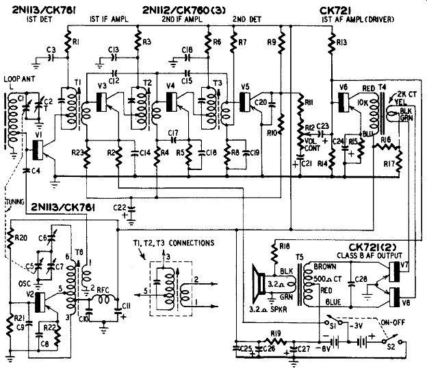
Fig. 609. Superheterodyne broadcast receiver.
Superheterodyne broadcast receiver
Parts list for portable broadcast receiver
Capacitors: C1-C5, dual 365-uuf variable; C2, built-in trimmer on section C1 of tuning capacitor; C3, C13, C14, C16, C17, C18, C19, .1-4 tubular; C4, 100-Api ceramic; C5, see C1; C6, 1250-Auf padder (Arco 309-M); C7, built-in trimmer on section C5 of tuning capacitor; C8, C9, .001-0 ceramic; C10, C25, .01-0 tubular; C11, C21, C23, C24, C26, C27, 25-,aµf electrolytic; C12, C15, 30-kiktf ceramic; C20, C28, .051 uf tubular; C22, 10-uf electrolytic.
Resistors: R1, R2, R3, R5, R6, R8, R9, 1000 ohms; R4, 150,000 ohms; R7, 39,000 ohms; R10, 56,000 ohms; R11, 220 ohms; R12, 25,000-ohm potentiometer; R13, 10,000 ohms; R14, 2200 ohms; R15, 820 ohms; R16, 5100 ohms; R17, 120 ohms; R18, 18,000 ohms; R19, 100 ohms, 1 watt; R20, 3900 ohms; R21, 27,000 ohms; R22, 1800 ohms; R23, 100,000 ohms.
Transformers and coils: L, transistor ferrite-loop antenna (Miller 2000); RFC, 2 1/2-millihenry rf choke; T1, T2, T3, 455- khz if transformer (Miller 2041); T4, transistor class-B driver transformer (Argonne AR-109); T5, transistor class-B output transformer (Argonne AR-119); T6, transistor oscillator coil (Miller 2020).
Transistors: V1, V2, Rf transistors (Raytheon 2NI13/CK761); V3, V4, V5, If transistors (Raytheon 2N112/CK760); V6, V7, V8, Af transistors (Raytheon CK721).
Miscellaneous: B, 6-volt battery tapped at 3 volts (see text); 51-52, dpst switch.
Fig. 609 shows the circuit of a conventional portable broadcast receiver transistorized throughout. This circuit, credited to Hazeltine, was used in the early Raytheon transistorized radio and is a strong favorite among experimenters. The author has adapted it to readily available components.
Raytheon p-n-p transistors are employed in all channels. Transistors having 10- mhz alpha cutoff (2N113/CK761) are used in the 1st detector and oscillator stages, V1 and V2, respectively. In the if amplifier and second detector (V3, V4 and V5) 5- mhz units (2N112/CK760) are employed and high-alpha low-frequency units (CK721) in the first af amplifier (driver) and push-pull class-B af output stages (V6, V7 and V8) .
The two-stage if amplifier is tuned to 455 khz. A tap on the primary winding of each if transformer (T1, T2, T3) is provided to match the 25,000-ohm output impedance of the transistor. The secondaries match the 600-ohm base-input impedance. To prevent oscillation in the if channel, the stages of this amplifier are neutralized automatically by fixed capacitors C12 and C15. The if channel has an overall power gain of 60 db. Negative dc bias (for the bases of the two if amplifier transistors) is obtained as avc voltage from the second detector V5 through the avc filter R10-C22-R23.
The second detector is a power type circuit providing a gain of approximately 10 db. This stage is coupled, through the volume-control potentiometer R12 and capacitor C23, to the af driver V6.
The push-pull class-B af output stage V7-V8 delivers 110 to 125 mw to a 3.2-ohm loudspeaker voice coil. Negative feedback for improving fidelity is supplied through resistor R18. It is imperative that the transformer connections follow the color coding indicated in Fig. 609, otherwise the feedback will not be of the proper phase for degeneration. Matching of transistors V7 and V8 with respect to collector current and alpha will reduce distortion. Fixed base-bias voltage supplied by the voltage divider R16-R17 minimizes cross over distortion. Decoupling to prevent motorboating is provided by the filter C26-R19-C27.
Oscillator V2 is a Hartley-type circuit. The oscillator signal is injected through capacitor C4 into the base of the first detector transistor V1.
A high-Q ferrite-rod type loop antenna (L) is employed. Tuning is accomplished with a two-gang 365-mtf variable capacitor C1-05, one section of which tunes the antenna while the other section tunes the primary of the oscillator transformer T6.
When the receiver will be used for private reception and loud speaker operation is not desired, 2,000-ohm headphones or a 2,000 ohm hearing-aid type earpiece may be connected in place of the primary of transformer T4. In addition to the loudspeaker, the following components may then be omitted: C28, R16, R17, R18, T4, T5, V7 and V8.
The numbers appearing on the terminals of the if transformers (T1-T2-T3) and oscillator coil assembly (T6) in Fig. 609 correspond to the manufacturer's labeling and must be followed strictly.
The receiver is powered by a 6-volt battery consisting of four size-D flashlight cells connected in series. A tap is taken at the-3-volt point. The total zero-signal dc drain of the receiver is 10 ma and the total maximum-signal current 34 ma. This low drain means a bat tery life of several hundred hours.
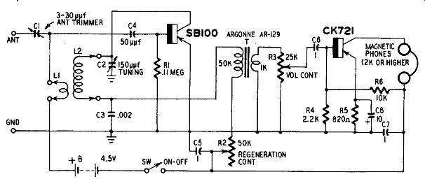
Fig. 610. All-wave regenerative receiver.
All-wave regenerative receiver
The high-frequency transistor makes a wide-range short-wave re generative receiver entirely feasible. Fig. 610 shows the circuit of a set of this type.
Using a Philco SB100 surface-barrier transistor as the regenerative detector, this receiver has a general-coverage tuning range of ...
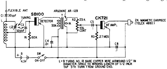
Fig. 611. High-frequency cueing receiver.
... 1,000 khz to 44 mhz in four bands: 1-2.7 mhz, 2.5-7 mhz, 6-17 mhz and 15-44 mhz. The circuit in Fig. 610 accommodates plug-in coils; however, the coils may be mounted permanently in the set with a two-gang rotary selector switch to provide a frequency-switching (band-switching) arrangement. Specifications for the coil combi nations (Ll-L2) may be found in the oscillator coil table (Table 4) in Section 4. The reader can alter the tuned-circuit constants for coverage only of restricted ranges such as the amateur bands.
A tickler type feedback circuit is employed. L1 is the low-impedance base tickler winding while L2 is the higher-impedance tuned-collector winding. Regeneration control is secured by varying the collector current with rheostat R2.
A single transformer-coupled af amplifier stage employing a p-n-p transistor (Raytheon CK721) gives headphone operation at approximately 2 mw. The operating point of this amplifier is stabilized by fixed dc bias (supplied by the voltage divider R4-R6) and the bypassed emitter resistor R5.
In operation, the 3-30- uf compression type trimmer capacitor C1 must be set for maximum signal response with minimum disturbing effect upon the tuned circuit, with the antenna in use.
Total direct-current drain from the 4.5-volt battery B is approximately 2.5 ma.
High-frequency cueing receiver
Fig. 611 shows the circuit of a cueing receiver, which takes its name from the fact that it may be worn on the person of an actor to receive cues from the director or stage manager. The pickup antenna is stitched into the costume or pinned inside a sleeve. It consists of a length of flexible insulated wire.
Operating an earpiece of the hearing-aid type, this receiver is designed to pick up signals from a nearby crystal-controlled radio phone transmitter operating on a carrier frequency of 27.255 mhz.
The transmitter can be quite simple and, because of its proximity, the receiver need not have high sensitivity nor the transmitter high power. The transmitter may be a small hand-carried unit placed in the wings of the stage or in the prompter's dugout.
The detector employs a Philco SB100 surface-barrier transistor; the af amplifier a Raytheon CK721. Total dc drain from the 4.5-volt battery B (which can consist of three of the smallest-size penlight cells connected in series) is approximately 1.2 ma. Small mercury cells may be used for stable voltage output throughout long life.
The shaft of the tuning capacitor C2, may be slotted for screw driver adjustment since this unit does not need frequent retuning to the single transmitter frequency. A small knob should be attached to the volume control potentiometer shaft R2 however, since this control needs occasional readjustment.