AMAZON multi-meters discounts
AMAZON oscilloscope discounts
THE high sensitivity of transistor circuits to both ac and dc signals I is an aid in the design of control equipment. This sensitivity provides high control efficiencies. The power economy of the transistor makes reliable and practical the unattended service of such equipment. Transistorized control devices may be operated from inexpensive batteries for long periods of time that often equal the shelf life of the battery. This ability divorces the equipment from power-line failures and allows compact, self-contained construction.
Even when transistorized devices are operated from the power line, the current drain (and consequently the operating cost, heat generated, size, and complexity) is considerably lower than with tube-type equipment.
The light weight and small size of the transistor, together with its operation from miniature batteries and in conjunction with miniature circuit components, suit the transistor naturally to circuits for model control. The high collector current of power transistors permits these units to be used directly as nonmechanical relays in some applications.
Practical control circuits are described in this section. These circuits may be used by themselves or in combination with other devices. While particular applications are specified for each circuit, the alert reader will discover many other uses to which each circuit may be put.
Sensitive dc relay
Fig. 801 shows the circuit of a sensitive direct-current relay employing a single transistor ( Sylvania 2N34) . A signal input of 47.5 pa dc will close the 1.6-milliampere relay (RY) in the transistor collector circuit.
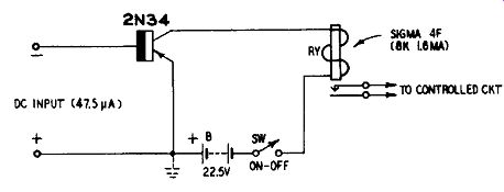
Fig. 801. Sensitive dc relay.
The transistor, connected as a common emitter, serves as a high-gain dc amplifier. It provides a current amplification of approximately 34 with the 8,000-ohm collector load presented by the relay coil. The input resistance of the circuit is 7,800 ohms, which means that the dc signal-input voltage is approximately 371 m-v.
The dc bias is supplied by a 22.5-volt battery, B. The initial, steady collector current is very slight and does not cause significant battery drain nor does it create any difficulty in operation of the relay.
The dc input signal power required by this circuit is only 17.6 microwatts. The dc power required to operate relay RY without the transistor would be 20.4 milliwatts. The amplifier circuit thus provides a power gain of 116.
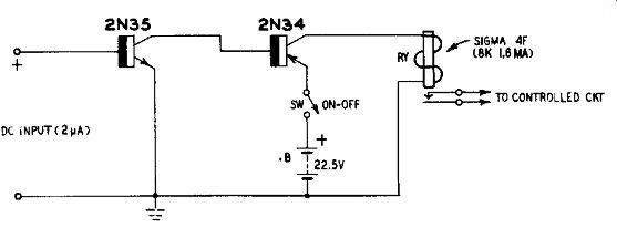
Fig. 802. Ultra-sensitive dc relay.
Ultra-sensitive dc relay When it is desired to operate at lower dc signal levels than the sensitivity of the simple relay circuit of Fig. 801 will permit, additional amplification may be employed. Fig. 802 shows the circuit of an ultra-sensitive circuit employing 2 stages of amplification. To use a single battery in the direct-coupled circuit, an n-p-n transistor ( Sylvania 2N35) is employed in the input stage and a p-n-p type ( Sylvania 2N34) in the output. This circuit has almost 25 times the sensitivity of the preceding one.
Direct current signal input is 2µa. The input resistance is 7,000 ohms and input voltage 14 my. Signal-input power is 0.028 micro-watt and the power gain is 735,000, or 58.7 db. Overall current gain is 800.
The single 22.5-volt battery B delivers 1.6 ma on closure of the relay. The current drain is negligible when the relay is not actuated (i. e., during absence of an input signal) , being the small collector current due to the i_co characteristic of the transistor.
This is a complementary-symmetry type of dc amplifier circuit.
The signal-input direct current flows into the base of the 2N35.
This causes a larger current to flow in the 2N 35 collector circuit, due to the beta characteristic. The 2N34 base-emitter circuit is the collector load of the 2N35, hence the amplified collector current of the latter flows into the 2N34 base and becomes amplified, in turn, in the 2N34 collector circuit which includes the coil of relay RY as its load.
Sensitive switching circuit for light-duty contacts
Switching operations often must be performed by light contacts which can carry only tiny amounts of current if sparking, pitting, and sticking are to be avoided. Currents often must be reduced also in full-sized contacts to prevent sparking in explosive or in flammable atmospheres. In either case, these light currents cannot be used directly to operate conventional relays.
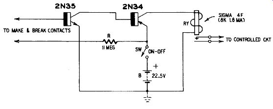
Fig. 803. Sensitive switching circuit for light-duty contacts.
Fig. 803 shows how the transistorized dc amplifier type of relay may be used to step up the small contact currents sufficiently to actuate a 1.6-ma relay, RY. The circuit also supplies approximately 2 microamperes for the contacts.
This circuit employs a 2-stage, direct-coupled amplifier similar to the one described in the preceding section and it has the same operating characteristics: overall current gain 800, signal-input power (handled by the contacts) 0.028 microwatt, and signal-input voltage 14 my. The 22.5-volt battery B supplies 1.6 ma for relay closure.
The small signal current ma power requirements of this relay circuit make it suitable for unconventional make-and-break contacts such as wires, electrolytes, foil or leaf strips, and light-duty thermostats. The circuit may be employed for temperature control by connecting an appropriate thermistor, thermocouple, or thermostat to its input leads. It may be employed also in electro chemical processes when the input leads are placed into an electrolyte, the relay sounding an alarm or stopping the process when the conductivity reaches the 2-pta level.
Sensitive ac relay
A bridge rectifier ahead of a transistorized dc amplifier and relay provides a sensitive ac relay. (See Fig. 804.)
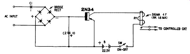
Fig. 804. Sensitive ac relay.
In this circuit, the ac is rectified by the bridge and the resulting dc applied to the input circuit of the transistor ( Sylvania 2N34) , base negative and emitter positive. Coupling capacitor C1 blocks any dc component which might be present in the input signal and would cause erroneous closure of the relay or damage to the rectifier. Capacitor C2 smooths the ripple in the rectifier output and thereby prevents chattering of the relay.
A signal-input voltage of 262 my rms will cause closure of the 8,000-ohm relay in the collector circuit. The relay coil draws 1.6ma dc for pickup. Current drain from the 22.5-volt battery (B) is negligible when there is no signal at the amplifier input terminals, being only the small component due to the i_co characteristic of the transistor.
For low-frequency and audio applications up to about 5 khz, the bridge rectifier may be of the copper-oxide type. Selenium diodes may be used to 50 khz. Above 50 khz, germanium or silicon junction diodes will be required. Germanium and silicon are, of course, satisfactory also for the low frequencies.
Sensitive rf relay
In Fig. 805, a 1N34 germanium diode rectifier (D) has been connected ahead of a single-stage amplifier-type relay. A radio-frequency signal applied to the input terminals of the circuit is rectified by the diode and the resulting direct current is smoothed by the bypass capacitor C and passed into the base-input circuit of the transistor ( Sylvania 2N341 .
The dc applied is negative to the base and positive to the emitter by poling the diode as shown in Fig. 805.
An rf input signal of 300 m-v rms applied to the input terminals of the circuit will cause the relay (RY) to close. Somewhat more signal voltage will be required at the high frequencies since the rectification efficiency of the diode decreases as the operating frequency increases. It falls to 30 % at about 40 mhz.
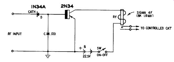
Fig. 805. Sensitive rf relay.
For the series-diode rectifier to operate correctly, a dc conductive path must be provided between the RF INPUT terminals by the output circuit of the radio-frequency source. If the latter cannot provide such a path, a 5,000-ohm resistor must be connected between the RF INPUT terminals. The sensitivity of the circuit will be approximately halved.
Dc drain from the 22.5-volt battery (B) is 1.6 ma when the relay closes and is negligible when there is no rf input signal.
Ultra-sensitive rf relay
In most instances, a single germanium diode and a sensitive transistorized dc amplifier-type of relay will be adequate for radio-frequency applications. However, when increased sensitivity is required, a higher-gain amplifier is needed. Fig. 806 shows a circuit of this type in which a 1N34 series-diode rectifier (D) is operated at the input of a two-stage direct-coupled amplifier employing a p-n-p transistor ( Sylvania 2N34) in the input stage and an n-p-n transistor ( Sylvania 2N35) in the output stage to operate the 1.6-ma dc relay, RY.
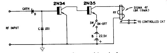
Fig. 806. Ultra-sensitive rf relay.
Diode D rectifies the rf signal applied to the input terminals of the circuit. Capacitor C serves to bypass the rf ripple component to ground. The anode of the diode is connected to the 2N34 base in order for this electrode to receive the negative dc output of the rectifier.
The rectified current flowing into the base is amplified in the 2N34 collector circuit by an amount governed by the beta of this transistor. Since the 2N35 base-emitter circuit constitutes the col lector load of the 2N34, this amplified current flows into the base of the 2N35 and becomes amplified still further in the 2N35 collector circuit. Twice-amplified current then flows through the coil of relay RY.
An rf input of 10 mv is required for closure of the relay. Thus, this circuit is seen to be 30 times as sensitive as the one previously described. The required input voltage will increase as the operating frequency is raised, since the diode rectification frequency falls off as the frequency increases, decreasing to approximately 30% at 40 mhz.
The output circuit of the radio-frequency source must provide a dc conductive path between the two RF INPUT terminals, otherwise the series-diode rectifier will not operate properly. If the rf source cannot supply such a path, a 5,000-ohm resistor must be connected between the RF INPUT terminals. The sensitivity of the circuit will be approximately halved. Shunt-diode rectification does not re quire the dc path but is notoriously insensitive.
Direct-current drain from the 22.5-volt battery (B) is 1.6 ma when the relay is closed and is negligible when there is no rf input signal.
Heavy-duty relay booster
In the preceding sections, a fairly sensitive dc relay has been shown in each circuit. This was done to keep safely within the maximum collector current and voltage ratings of the transistors.
When a heavier-duty relay is preferred, a power transistor must be employed in the output amplifier. Fig. 807 shows a circuit of this type incorporating a 6-volt, 80-ohm relay (Potter & Brumfield
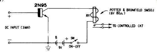
Fig. 807. Heavy-duty relay booster.
The relay constitutes the collector load of an n-p-n type power transistor ( Sylvania 2N95) and is closed by 75 ma dc from the 9-volt battery B. A signal-input of 3 ma dc flowing in the base-emitter circuit of the transistor is amplified to 75 ma in the collector circuit and picks up the relay. This operation represents a current amplification of 25.
The input resistance of the circuit is approximately 50 ohms.
From this factor and the input-current requirement, it follows that the dc signal-input power required for closure of relay RY is 0.45 mw and the overall power gain of the circuit is 45.5, or 16.6 db.
Battery B delivers 75 ma to close the relay. In the absence of an input signal, however, the steady collector current is 5 ma or less and will be lower still when the dc signal source has low resistance compared to the 50-ohm input resistance of the circuit.
Sensitized heavy-duty relay booster
Additional gain is provided in the circuit shown in Fig. 808 by an input amplifier stage employing a conventional n-p-n transistor ( Sylvania 2N35) which is direct-coupled to the p-n-p power transistor ( Sylvania 2N68) . An input-signal current of only 110 u-a will cause closure of the 6-volt, 80-ohm, 75-ma relay, RY. This represents an overall current gain of 680.
The amplifier circuit is the direct-coupled complementary-symmetry type described in several of the preceding sections. The 2N68 base-emitter circuit is the collector load for the 2N35 while the coil of relay RY constitutes the 2N68 collector load. The first amplified input current thus flows into the 2N68 base and the second amplified current through the relay coil.
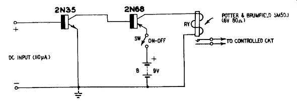
Fig. 808. Sensitized heavy-duty relay booster.
The dc drain from the 9-volt battery (B) is approximately 78 ma when the relay closes and is negligible in the absence of an input signal, being due at that time only to the ieo characteristics of the two transistors.
Sound-operated relay
Fig. 809 shows the circuit of a high-sensitivity, sound-actuated relay circuit in which the relay remains closed as long as a sustained sound is directed into the microphone. The circuit comprises a high-gain audio amplifier with class-B 100-mw output, a diode rectifier, and a 2.6-ma 13-ohm dc relay (Barber-Colman AYLZ 4436S Micro-positioner) .
The amplifier, operated from a crystal microphone, has an overall power gain of approximately 112 db. Transformer coupling is employed throughout for maximum gain per stage. The audio gain control potentiometer R4 serves as a sensitivity control. P-n-p type transistors (Raytheon CK721 and CK722) are employed.
The audio output of the amplifier, available at the 8-ohm secondary of transformer T4, is rectified by germanium diode D (Raytheon CK705) and smoothed by capacitor C5.
The high sensitivity of this circuit permits operation from low-intensity sounds when R4 is set for maximum gain. When operation is desired at a higher sound level, the SENSITIVITY CONTROL may be set accordingly by experiment to discriminate against lower-intensity ambient noise.
If sounds of only one pitch are to be used for control purposes and selectivity is desired with respect to all other pitches, suitable L-C type bandpass filters may be inserted in the base-input circuits of either or both of the first two stages of the amplifier.
Light-operated relay
Photoelectric relays have myriad uses in industrial and household electronics and in hobby pursuits. The transistorization of these light-controlled relay circuits has increased their effectiveness and widened their field of application.
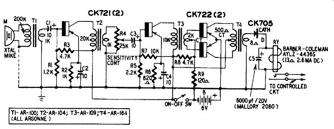
Fig. 809. Sound-operated relay.
Fig. 810 shows the circuit of a sensitive, light-operated relay employing a self-generating photocell and a two-stage direct-coupled transistor amplifier. This circuit may be operated from low-intensity light sources or from bright illumination, depending upon the setting of the sensitivity control, R.
The light-sensitive component in this circuit is the photocell, PC.
A self-generating type is employed to obviate the necessity for a bias current. Light energy generates a voltage directly as a result of semiconductor action in the cell. A number of selenium and silicon photocells are available to the experimenter. Typical units...
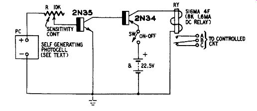
Fig. 810. Light-operated relay.
...which will give excellent performance in this circuit are International Rectifier Corp. type DP-5 selenium and Natfab type P-100 silicon.
The photocell must be connected so that its positive dc output is applied to the base of the first transistor ( Sylvania 2N35) through rheostat R. When the cell is illuminated, direct current proportional to the light intensity passes into the 2N35 base and becomes amplified in the collector circuit of this transistor. The amplified current flows into the base of the second transistor ( Sylvania 2N34) and becomes amplified further in its collector circuit. This current then actuates relay RY.
The relay is provided with two stationary contacts, one of which is in contact with the movable armature when the latter is at rest.
By making the proper connections to the three output terminals (A, B, C) , the relay may be caused to open or close an external circuit, as desired. The following two examples illustrate use of the connections:
EXAMPLE 1: Illumination of photocell actuates external device Make connections to output terminals A and C. As long as the photocell is darkened, the relay contacts are separated and the external circuit is open. When the cell is illuminated, the relay armature moves to the upper contact and the circuit through the external device is closed.
EXAMPLE 2: Interruption of light beam actuates external device Make connections to output terminals B and C. As long as the photocell is illuminated, the relay armature is held against the upper contact and the external circuit is broken. When the light beam is interrupted, current ceases to flow in the relay coil, the armature drops to the lower contact and the circuit through the external device is closed.
During closure of the relay, the 22.5-volt battery (B) delivers approximately 1.65 ma. When the photocell is darkened, the current drain from the battery is negligible, being only the small value governed by the ie0 characteristics of the transistors.
Photoelectric counter In the circuit shown in Fig. 811, a photoelectric counter has been obtained by adding to the light-controlled relay circuit a five-digit electromechanical counter and an ac-operated power supply. The transistorized photoelectric amplifier is identical with the circuit given in Fig. 810.
The power supply is a voltage tripler consisting of the 6.3-volt filament-type transformer (T) , three 1N34 germanium diodes and three 10-0 50-volt electrolytic capacitors (C1, C2, C3) . The open- circuit dc output of this tripler circuit is 26.7 volts which is three times the peak value of the 6.3 volts delivered by the transformer secondary. At full current load, when relay RY closes, the voltage drops to approximately 24.
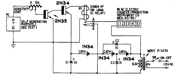
Fig. 811. Photoelectric counter.
The 6-volt ac counter is connected to the transformer secondary through the relay contacts. When wired as shown in Fig. 811, the counter will advance one digit each time the photocell is illuminated, since the relay armature then moves to the upper contact A.
To operate from interruptions of a light beam, however, as in counting opaque objects, the counter must be connected instead to the lower relay contact B.
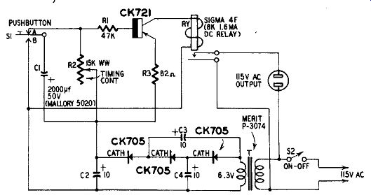
Fig. 812. Phototimer.
Phototimer
Fig. 812 shows the circuit of a phototimer which provides time intervals adjustable between 1 and 48 seconds. In addition to its intended use as a phototimer, this device may be used as a general purpose timer.
The circuit is operated from the ac power line. The dc power supply is a voltage tripler consisting of the 6.3-volt filament-type transformer (T) , three CK705 germanium diodes, and three 10-1.if 50-volt electrolytic capacitors (C2, C3, C4) . The open-circuit dc output of this tripler circuit is 26.7 volts, which is three times the peak value of the 6.3-volt transformer secondary voltage. At full current load, when relay RY closes, the voltage falls to approximately 24. When the relay closes, 115 volts appear at the terminals of the female output receptacle into which may be plugged the photographic enlarger, printing box, or other ac-operated device which is to be timed.
Timing action is afforded by the 2,000 u-f capacitor (C1) and the 15,000-ohm rheostat (R2) . Pushbutton switch S1 normally is in the position shown, with its arm against the upper contact A. To initiate operation S1 is depressed momentarily, causing C1 to be charged from the dc power supply through switch contact B. When Si then is released, the voltage due to the capacitor charge is applied to the base-input circuit of the transistor (Raytheon CK721) through resistors RI and R3. Current flowing into the CK721 base becomes amplified in the collector circuit of this transistor and picks up relay RY.
From this instant on, capacitor C1 discharges through R2 and the transistor input circuit at a rate determined mainly by the resistance setting of R2. When the capacitor voltage falls below the magnitude necessary to maintain the proper level of base current, the relay coil current drops below its hold-in value and the relay opens, de-energizing the 115-volt outlet. A dial attached to rheostat R2 accordingly may be calibrated to read directly in seconds.
Miniature-motor control
Fig. 813 shows a simple high-gain dc amplifier arrangement for starting, stopping and varying the speed of a miniature, model type dc motor. The input-signal current for top speed of the motor (Lafayette F-177) is only 200 u-a to and this signal may be derived from a number of convenient control sources, allowing this circuit to be used in model operation, remote-control systems, servomechanisms and instruments. The amplifier SENSITI VITY CONTROL rheostat (R) serves as a speed control for the motor.
The motor constitutes the collector load of the output transistor ( Sylvania 2N68) . A power transistor is required in this stage, since the motor current is 0.25 ampere. The input amplifier stage, which is direct-coupled to the power stage, employs an n-p-n transistor ( Sylvania 2N35) .
Dc drain from the 7.5-volt battery (B) is approximately 255 ma when the motor is running at full speed. When the DC INPUT signal is zero, this current drain drops to approximately 15 ma and is due to the ir characteristics of the two transistors.
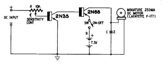
Fig. 813. Miniature-motor control.
General-purpose radio control relay
Radio-controlled relays find many commercial and amateur re mote-control applications including model control, safety-alarm operation, intrusion (burglar) alarms, garage-door opening, electronic baby sitting, etc. Fig. 814 shows a receiver relay circuit for radio control involving an unmodulated carrier.
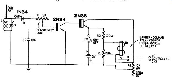
Fig. 814. General-purpose radio control relay.
The inductance of coil L and capacitance of variable capacitor C1 are chosen to resonate at the desired carrier frequency. A vertical rod or whip antenna will suffice in most instances, but other antennas are permissible.
The picked-up rf signals are rectified by the 1N34 germanium diode which is so poled in the circuit (anode output) that its negative dc output voltage is applied to the base of the p-n-p input transistor ( Sylvania 2N34) . Capacitor C2 serves as an rf bypass.
Rectified current passes into the 2N34 base after being limited by the SENSITI VITY CONTROL, rheostat RI. This current becomes amplified in the 2N34 collector circuit. The base-emitter input circuit of the n-p-n output transistor ( Sylvania 2N35) constitutes the collector load of the 2N34 so that the amplified collector current of the 2N34 passes into the 2N35 base. This current then is amplified further in the 2N35 collector circuit and actuates the dc relay RY.
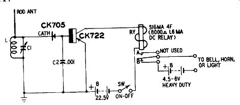
Fig. 815. Carrier failure alarm.
Because of the low current requirement of the relay coil, a four-arm resistance-bridge circuit is needed to balance the static zero-signal collector current out of this coil, otherwise the relay will be closed at all times. The process is the same as zero-setting a vacuum-tube voltmeter. The bridge consists of resistors R2, R3, R4 and the internal collector-to-emitter resistance of the 2N35 transistor.
With zero-signal input to the circuit, the ZERO-SET rheostat R4 is adjusted to balance the bridge. This null point is indicated by the opening up of the relay contacts.
At the maximum-gain (minimum-resistance) setting of SENSITIVITY CONTROL rheostat RI a 1-mv rms radio-frequency signal at the antenna will cause relay RY to close. Lower-intensity signals are ineffective, not because of lack of sensitivity in the amplifier, but because most semiconductor diodes cease to rectify at levels under 1 mv.
Current drain from the 3-volt battery (B) is approximately 13 ma. Most of this is current through the bleeder (voltage divider) R2-R3.
Carrier failure alarm
A sensitive device for signaling carrier interruption is invaluable around radio stations. Simple diode detectors driving sensitive dc relays have been used for this purpose but are so insensitive that they require tight coupling to the transmitter.
The carrier failure alarm circuit shown in Fig. 815 employs a diode detector but follows it with a dc amplifier to build up the feeble dc output of the diode. This amplification permits the use of a small antenna (usually a vertical rod or whip) for signal pickup and a dc relay RY, the sensitivity of which does not exceed 1.6 ma.
Inductance of coil L and variable capacitor C1 are chosen to resonate at the carrier frequency. The diode (Raytheon CK705) is poled in the circuit for anode output so that the base of the transistor (Raytheon CK722) receives a negative voltage when the diode rectifies an rf signal. The resulting direct current flowing into the CK722 base becomes amplified in the collector circuit and picks up the relay.
The 22.5-volt battery (B) delivers 1.6 ma when the relay is actuated. In the absence of an rf input signal, the current drain is negligible, being the low value governed by the characteristic of the transistor.
Impulse counter
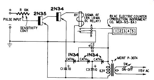
Fig. 816. Impulse counter.
Fig. 816 shows the circuit of a device for counting uni-polarity pulses. These pulses-which may be as low as 14 my or 2 pa (0.028 microwatt) when the SENSITIVITY CONTROL rheostat (R) is set to its high-gain (low-resistance) position-may be derived from a photo cell, make-and-break contactor, rectified radio signals, or any other source delivering either random or uniform pulses. The maximum counting speed is limited by the response of the five-digit electro mechanical counter connected to the output and is 600 counts per minute. The total possible count is 99,999.
The signal pulses are presented to the PULSE INPUT terminals with the upper terminal positive. Pulse current flowing into the base of the input transistor ( Sylvania 2N35) through rheostat R becomes amplified in the collector circuit of this transistor. The base-emitter circuit of the second transistor ( Sylvania 2N34) constitutes the collector load of the 2N35, hence the amplified current flows into the 2N34 base. Further amplification occurs in the output stage so that the 2N34 collector current flowing through the coil of the relay (RY) is sufficient to pick up the relay. On closure of the relay, 6.3 volts ac, derived from the secondary of the transformer (T) are applied to the counter.
The power-line-operated power supply is a voltage tripler consisting of the 6.3-volt filament-type transformer (T) , three 1N34 germanium diodes and three 10-uf 50-volt electrolytic capacitors (C1, C2, C3) . The open-circuit dc output of this tripler circuit is 26.7 volts which is three times the peak value of the 6.3-volt transformer secondary voltage. At full current load, when relay RY closes, the voltage is approximately 24.