APPENDIX A
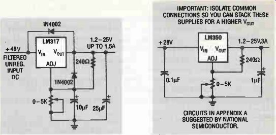
----IMPORTANT: ISOLATE COMMON CONNECTIONS SO YOU CAN STACK THESE SUPPLIES FOR A HIGHER V_out ; CIRCUITS IN APPENDIX A SUGGESTED BY NATIONAL SEMICONDUCTOR.
These excellent regulators are designs suggested by National Semiconductor. They appear in their Voltage Regulator Handbook. Important: See text discussion before constructing the circuits!
APPENDIX B
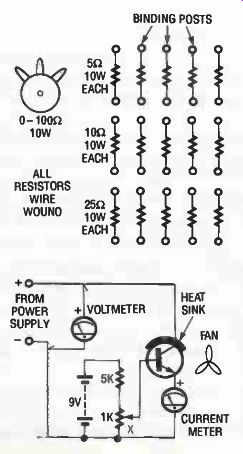
Examples of substitute load resistor circuits. At bottom a bipolar power transistor is used as a substitute load resistance in DC circuits.
APPENDIX C
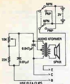
Schematic diagram for an in situ tester. The tester produces a tone when a good transistor is added to the circuit.
APPENDIX D
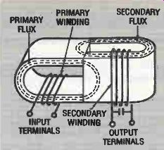
Note that the geometry of the transformer above is such that the primary flux does not link the secondary winding and that the secondary flux does not link the primary winding. (Accordingly, the classical flux coupling is zero). However, note that the primary flux does modulate the reluctance associated with the secondary flux and hence the primary does modulate the inductance of the secondary. This modulation can be achieved only by transferring electrical power from the primary to the secondary. This power in turn sustains the secondary oscillations and delivers power to the load. It is this unique parametric power transfer mechanism that makes the Paraformer a revolutionary new component. (Courtesy of Wanless Electric Co.)
APPENDIX E
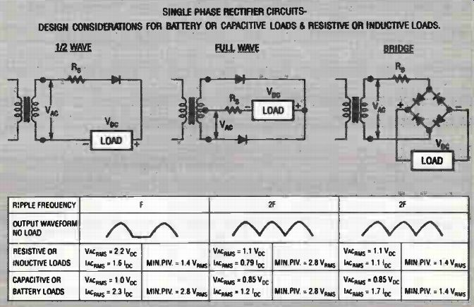
SINGLE PHASE RECTIFIER CIRCUITS DESIGN CONSIDERATIONS FOR BATTERY OR CAPACITIVE LOADS & RESISTIVE OR INDUCTIVE LOADS.