CLOSED-LOOP REGULATOR CIRCUITS
There are two types of closed-loop regulator circuits that are popular at this time: analog regulators and switching regulators. The best way to study them is to start with the individual circuits that are used in their construction.
An Overall View of Closed-Loop Regulator Systems
Figure 27 shows a block diagram of an analog regulator; and, a block diagram of a switching regulator. Observe that they are both closed-loop systems. A most important difference between them is in the fact that an oscillator is required for the switching regulator. Another important difference is that the analog regulator uses a continuous bias control to maintain a constant output voltage. The switching regulator usually makes use of a pulse width modulator for the same purpose.
The switching regulator is not the only power supply that uses an oscillator. Inverter and converter circuits have oscillators. Uninterruptible power supplies and scan-derived sup plies also use oscillators.
There are some advantages of the switching regulator over the analog type:
• Power supplies are more efficient when they are switched on and off as opposed to continuous duty.
• Since the frequency associated with the on/off switching is higher than the 60-Hertz or 120-Hertz ripple frequency of most analog supplies, the ripple is easier to filter. That, in turn, means that smaller and less costly components can be used in the filtering circuitry. It also means that the complete switching regulator can be built into a smaller package.
The disadvantages of the switching regulator are:
• There is a higher cost in the design and in the manufacturing because of the more complicated circuitry.
• As a rule the switching regulator is more difficult to troubleshoot. That can mean more delay in getting the circuit back into operation.
Because of the switching circuitry and the associated switching transients, switching regulators are noisier than analog types. Transient filters must be used if the noise is a problem.
A brief review of the operation of individual circuits follows.
CIRCUITS COMMON TO ALL CLOSED-LOOP REGULATORS
Refer again to the analog regulator in Figure 27. A good way to analyze analog and switching regulators is to start with the circuits that are common to both. Be sure you know how to recognize the circuits common to all regulator circuits, and know how to troubleshoot them! Think about this: a closed-loop voltage-regulated power supply compares the power supply output voltage with a reference voltage. If the two voltages are the same no corrective action is needed. If the voltages are not the same the regulator will adjust the output voltage to make them the same.
Regulator Circuits
In high-priced regulated supplies the reference voltage is obtained from a separate supply.
However, in most regulator circuits it is usually made with an open-loop regulator using a zener diode in series with a resistor.
The output voltage of the regulator circuit must be sensed so that it can be compared with the reference voltage. So, you can expect to find a sense circuit in regulators. Figures 8 and 9 show examples. In a typical sense circuit, the sense voltage is lower than the supply voltage.
There has to be a voltage comparator in a closed-loop regulator circuit. It compares the sensed voltage with the reference voltage. Refer again to Figures 8 and 9.
There has to be a control component. In an analog regulator it is a power amplifier that can be used to adjust the output voltage if a corrective action is needed. It is often called the series pass amplifier.
All of these things are needed in an analog closed-loop voltage or current regulator circuit.
There may be a protective device or protective circuit. A fuse or circuit breaker is an electro mechanical protective device. An electronic crowbar circuit may be used as a very fast, non-mechanical, protective circuit. The purpose of the protective device or protective circuit is to prevent a wrong output voltage and/or current from destroying components in the load circuit. Any of these circuits or components may be the cause of a regulated supply not working properly!
OPERATION OF THE ANALOG VOLTAGE REGULATOR CIRCUIT
Refer again to the analog regulator in Figure 27. The output voltage is sensed and compared with a reference voltage. If there is a difference in the two voltages that difference is amplified and fed back to control the conduction of the series-pass transistor.
There is a limit to the amount of amplification that can be used in the regulator. Too much feedback will cause oscillations and a condition known as "hunting". Figure 28 shows the output of a supply that has too much feedback amplification when there is a step-voltage change in the input. The complete supply becomes an oscillator for a brief time. You can easily recognize the oscillation frequency because on an oscilloscope display, it is higher than the normal ripple frequency.
If the feedback amplification is not high enough the supply will be slow to respond to change in the supply voltage. The supply is said to have a poor slewing capability. In that case the output voltage of a regulator can undergo undesirable transient voltage changes because the regulator is not fast enough to prevent them.
The amplified difference between the sensed and reference voltages is inverted and de livered to the base of the series-pass transistor. So, if the sense voltage is higher than the reference voltage the forward bias on the transistor is reduced. On the other hand, if the sensed voltage is lower than the reference voltage the forward bias on the transistor is in creased. You can consider the series-pass transistor as being a voltage-operated resistor.
A decrease in the power amplifier bias control voltage increases the resistance of the power amplifier. This positions the variable-resistor arm and lowers the supply output cur rent. The reduced current lowers the voltage across the output load resistance. The overall result of the operation just described brings the output voltage back to the required value.
The bias control voltage decreases the resistance of the power amplifier when the output voltage is too low.
OPERATION OF THE SWITCHING REGULATOR
Refer again to Figure 27. Unlike the analog regulator which has a continuous output voltage control, this type is switched on and off to regulate the output power. The on time is controlled by the duty cycle control. That, in turn, controls the power supply output. Ob serve the waveforms for low and high output power shown in Figure 29.
As with the analog regulator, the output voltage is sensed and compared with the reference voltage. The difference voltage (if it exists) is amplified and used to control the duty cycle of the pulse control circuit. As shown in Figure 29, the RMS value of the voltage or cur rent is higher for a higher duty cycle. That translates to a higher power supply DC output voltage for higher pulse RMS values.
The oscillator delivers pulses to the duty cycle control circuit. Note that the oscillator output is not changed by the control signal. The change in duty cycle occurs inside the control circuit in this version of the switching regulator. Using a signal or variable voltage to control the duty cycle is called pulse width modulation, or, PWM. The overall result is that a rise in the output voltage above the required voltage causes a decrease in the duty cycle of the pulses. The result is a lowering of the RMS value and corresponding lowering of the output voltage back to the required value.
If the output voltage goes below the required value the duty cycle of the pulses is in creased. That results in the output voltage rising to the required value.
If you are troubleshooting a switching regulator that has no output, one of the first steps is to scope the oscillator output. If there is no oscillator signal the system cannot operate.
As with the analog regulator, the output of the unregulated supply should be one of your first measurements when troubleshooting an electronic system. If the preliminary tests don't work, open (or, defeat) the loop and test the circuits one-at-a-time. Start with the oscillator.
The oscillator in a switching regulator will be some kind of relaxation oscillator-often a multivibrator.
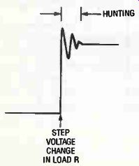
Figure 28
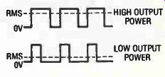
Figure 29
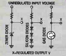
Figure 30
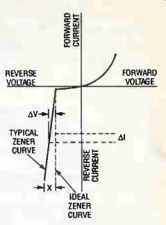
Figure 31
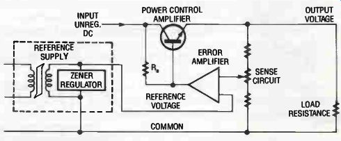
Figure 32
TROUBLESHOOTING ANALOG REGULATORS
Think about this again: An analog regulated power supply compares the output voltage with a reference voltage. See Figure 27. If the two voltages are the same no corrective action is needed. If the voltages are not the same the regulator will automatically adjust the output to make them the same.
There has to be a reference voltage somewhere in the regulator.
The output voltage must be sensed so that it can be compared with the reference voltage.
So, you can always expect to find a sense circuit in the regulator.
There has to be a voltage comparator to match the sensed voltage against the reference voltage.
There has to be a control circuit that can be used to adjust the output voltage if a corrective action is needed.
All of these things are needed in an analog voltage regulator circuit. There may also be a current regulator in the regulator section of the supply. Finally, there may be a protective circuit to prevent the output voltage and/or current from being the wrong value.
Any of these circuits may be the cause of an analog regulated supply not working properly! So, locate these circuits and test them when you begin to work on the supply. Some methods of doing that are discussed in the following paragraphs.
The Reference Circuit
It is customary to use an open-loop regulator to obtain a reference voltage. At one time neon lamps were used to obtain a reference voltage. Today the favored component is a zener diode. An example is shown in Figure 30. The reference circuit is connected across the DC voltage source at some point in the regulator near the output.
The voltage across the zener diode is nearly constant even through the DC input voltage may vary over a limited range. Also, limited changes in the value of load resistance will not seriously affect the voltage across the zener diode and load resistance.
Figure 31 shows a typical zener diode characteristic curve. Observe that the voltage is not precisely constant. When there is a small change in current (delta I) through the zener diode, there is an accompanying slight voltage change ( delta V). The problem created by delta V is magnified by the fact that the zener reference circuit gets its voltage from the DC source, and, that is the voltage the closed-loop regulator is sup posed to regulate. Furthermore, changes in the regulator load current can slightly affect the voltage across the zener diode.
To get around the fact that the zener circuit output voltage is not precisely held to a constant value, expensive laboratory supplies often are designed with a separate supply as a reference source. This is shown in Figure 32.
You may wonder why the separate zener reference voltage is made with a pre-regulator (such as a constant-voltage transformer). Why not just use the pre-regulator in the circuit of Figure 27? Although that is done in some supplies, the answer is in the cost. The lower power requirement in the reference translates to less expensive pre-regulator transformers.
If you have a variable AC voltage source on your bench-such as a autotransformer (Variac)--it is a good idea to measure the zener voltage when the AC input voltage is varied from 100V to 125V. (The manufacturer may specify a wider range of input voltages.) The zener voltage should be constant-or, very nearly constant-when the AC voltage is varied over that range.
You can replace a zener diode with one that has a higher power rating. Of course, the voltage rating must be the same. Never use one with a lower power rating; and, never try to get a higher power rating by connecting zener diodes in parallel.
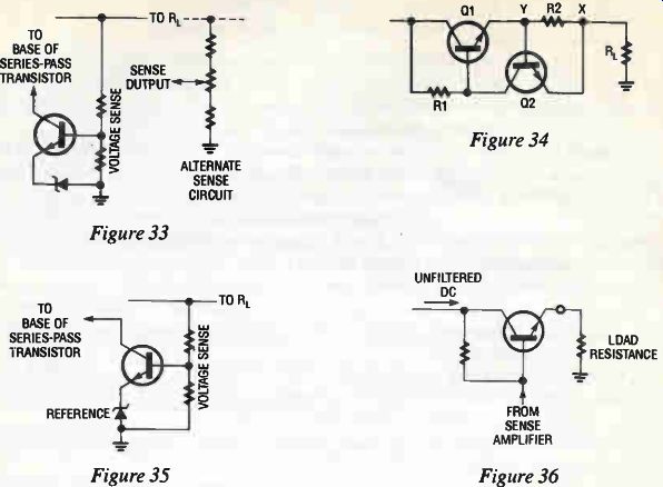
Figure 33-36
SENSE CIRCUITS
There are two types of sense circuits that may be used in regulated power supplies: voltage sense and current sense. Both types are shown in Figures 33 and 34.
Voltage Sense Circuit
The reference voltage must be compared with the power supply output voltage, or, with a voltage that is proportional to the output voltage. The supply output voltage is usually sensed by a resistive voltage divider circuit like the one shown in Figure 33.
The variable resistors used in some sense circuits have a nasty habit of opening at the contacts. That makes it impossible for the regulator to work. Make a mental note to make sure the variable resistor is operating smoothly-even though it is not the source of the trouble you are working on.
Current Regulation
Figure 34 shows the basic circuit for current regulator. This circuit is often used in con- junction with a voltage regulator. All of the load current is delivered to point (x). There it splits with part of it flowing through R2 and Q1. Resistor R2 is a low value of resistance used to sense the load current. Assuming electron current flow, point (x) will be negative with respect to point (y). That makes the base of Q2 positive with respect to its emitter. The amount of positive forward bias depends upon the amount of load current through R2.
The collector current of Q2 flows through R1 and sets the bias voltage on the base of Q1 . If the load current tries to increase, Q2 conducts harder and that, in turn, decreases the forward bias on series pass transistor Q1. The result is that the current through Q1 decreases and returns the load current to the rated value.
A decrease in the load current will increase the forward bias on Q1 and return the load current to its rated value.
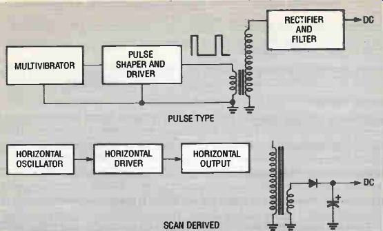
Figure 37 --PULSE TYPE ; SCAN DERIVED
Voltage Sense Amplifier Circuit
Figure 35 shows a typical sense amplifier. The sense voltage and the reference voltage are compared in a voltage sense amplifier circuit. If the two voltages are the same there is no corrective action taken. If the sense voltage is higher or lower than the reference the closed loop circuit adjusts the output of the supply until those voltages are matched.
In order to get a well-regulated supply it is necessary to amplify the difference between the sensed and reference voltage. That way the regulator can take action for very small change in the output of the supply. That is why a sense amplifier is used. (It is sometimes called a difference amplifier.) Operational amplifiers have a differential amplifier input so they can be used as sense amplifiers. Another advantage of using an operational amplifier is its high gain. The high gain makes the regulator very sensitive to small changes in output voltage.
You have to be careful when you troubleshoot any of the types of sense amplifiers. It might seem that an obvious approach would be to open the load resistance to produce a rise in the output voltage. Then, check the output of the sense amplifier to see if it reacts to the increased voltage at the output. That would be a very bad practice! The Power Amplifier The power amplifier controls the output current and voltage of the supply. See Figure 36. As with all electronic components that get very warm, the power amplifier is a very likely problem in a supply when the symptom has an incorrect output voltage. Because of its high operating temperature, the defect is likely to be catastrophic. In other words, when it be comes defective it is completely destroyed.
A quick check for a defective power transistor is to measure the emitter-collector voltage. It should be about one volt. Due to its internal construction a short circuit between the emitter and collector is a likely source of power amplifier failure.
A high voltage across the power amplifier is another indication that it is defective. A higher-than-normal temperature (due to an internal short circuit) is also a clue to a defective amplifier.
You have to be very careful when replacing a power amplifier. In most applications the transistor case must be isolated from the supply chassis. Silicon grease is usually required to insure that the heat from the transistor is transferred to the heat sink.
A problem that can occur with replacement is that the technician over-tightens the stud.
That causes an internal stress and early loss of the replacement amplifier. On the other hand if the amplifier is not sufficiently tightened there will be a poor thermal and/or electrical connection. That will also cause an early loss of the replacement transistor.
At one time it was recommended that a torque wrench be used to tighten the stud. Unfortunately, few technicians had the necessary torque wrench. Today, the studs are tightened by using the "feel" of the wrench. Fortunately, there is a wide allowable tolerance.
TROUBLESHOOTING SWITCHING REGULATORS
Compare the two regulator circuits in Figure 27 and observe that the switching regulator has three additional circuits: a startup circuit, an oscillator circuit and a duty cycle circuit. (The power amplifiers are very similar.) Therefore, the troubleshooting discussion for analog regulators also apply to switching regulators. Only three additional circuits need to be discussed separately.
The Startup Circuit
If the oscillator gets its operating voltage from the output of the switching regulator it is obvious the circuit cannot get started. There is no output voltage unless the oscillator is working; and, the oscillator cannot work unless there is an output voltage.
The startup circuit is sometimes called a kickstart. It supplies voltage to the oscillator until the output of the regulator can take over.
The startup circuit is powered by a DC input from the unregulated DC supply. If there is no output from the regulator make sure the oscillator is producing an output signal. If not, look for the DC input from the startup circuit. The startup circuit is diode switched. When the circuit is first energized a portion of the unregulated voltage forward biases a diode.
That applies a DC operating voltage to the oscillator. Once the regulator output goes above the voltage providing the forward biasing, the diode is reverse biased and the unregulated voltage is disconnected from the startup circuit.
If there is a DC input to the startup circuit, but no DC output when the system is first energized, concentrate on the startup circuit.
The Oscillator Circuit
Energize the oscillator from a bench supply to make sure the regulator has not been shut down by a crowbar circuit. If the oscillator doesn't work with an input from the bench sup ply, concentrate on the oscillator circuit.
The Duty Cycle Control
Vary the sense input and see if there is a change in duty cycle. The best way to do that is to disconnect the sense circuit. Vary the sense input to the comparison amplifier using a variable output bench supply.
If there is no change in the output of the comparison amplifier or duty cycle control concentrate on those circuits.
One of the best ways to troubleshoot the three circuits just mentioned is to make careful voltage measurements. Consult the schematic diagram of the system for typical measurement values.
Remember that, as with analog regulators, you have to open (or defeat) the feedback loop to troubleshoot the switching regulator.
PULSE-OPERATED AND SCAN-DERIVED SUPPLIES
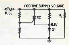
Figure. 38 Pulse-Operated Type
There are some power supplies that are closely related to switching types, but, they deserve a separate classification. They can be called pulse supplies. They include the scan derived and chopper types.
An important feature of these supplies is that they utilize Faraday's Law of Electromagnetic Induction.
Clearly stated, the amount of induced voltage (V) in a coil at any instant of time can be in creased by increasing the number of turns of wire in the coil. Also, it can be increased by in-creasing the rate at which the magnetic field is moving across the coil. (In textbook terms the magnetic flux lines are said to be "cutting across" the turns of wire in the coil.) In the example of Figure 37 the current in the primary winding has a pulse waveform. That rep resents a rapid change of current in the primary, and, a rapidly changing magnetic field (do/dt) around the primary winding. That rapidly changing field cuts across the secondary winding and produces the high secondary voltage.
So, the high secondary voltage of the transformer in Figure 37 is produced by a large number of turns and a rapidly changing magnetic field around the primary.
In practice, the current in the primary winding can be high and cause a rapidly changing flux to cut across the secondary.
Scan-Derived Type
Figure 37 also shows the principle parts of a scan-derived power supply. A relatively few turns of wire in the low-voltage winding of the flyback transformer is used to produce a secondary AC voltage. That voltage is rectified to produce the scan-derived DC supply voltage.
Here are some important advantages of the scan-derived low-voltage power supply over other types:
• The frequency of the sweep is approximately 15,750 Hertz. That makes the ripple of the supply easier to filter. So, smaller and lower-cost components can be used in the low pass ripple filter.
• The sweep is are available from the horizontal sweep section. Therefore it is not necessary to use a separate oscillator as in some switching regulators.
• Compared to using a power transformer operated from the 60 Hertz power lines, a few turns of wire on the flyback transformer is a much less costly and less bulky way to get the voltage for operating the low voltage supply.
• The fact that the supply uses a rapidly-changing sawtooth current rather than sine waves makes it a more efficient supply.
If the scan-derived supply is delivering too much current (because of a defect in the low voltage output circuitry) the high current can affect the magnetic circuit in the flyback transformer. That, in turn, will seem to indicate there is something wrong in the horizontal scanning circuit or in the high-voltage circuit.
Before you tear into the flyback transformer circuits, use your oscilloscope to check the waveform of the voltage delivered to the scan derived supply. Any change in the amplitude or shape of the pulse means there is something wrong.
As a further check, disconnect the circuits that get their low voltage from the scan-de rived supply winding. Use your bench supply to deliver the required voltage and current to the disconnected circuits. If the circuit works, the trouble is in the flyback transformer. If the circuits that receive their voltage from this supply don't work with the bench supply you know the trouble is in one of those sections.
I will get letters if I don't warn you that there are some mighty High Voltages around the flyback transformer. Don't try to 'scope those high voltages unless you are sure your oscilloscope can handle them.
Chopper Supplies
In the period between the 1930's and middle 1950's the tube-operated car radios could not operate directly from the battery. Toward the end of that period some of the radios operated with tubes that used 12V for the plates, but, the most important step to using the car battery for a "B" supply was the introduction of the transistor.
Returning to the problem of the earlier days-that is, the problem of operating vacuum tube equipment from the car battery-there were two approaches.
Early Chrysler cars used a dynamotor (mounted in the trunk) to get the necessary high voltages. A dynamotor is a DC motor and DC generator mounted on the same shaft. The motor operated directly from the car battery and the generator delivered the higher voltage needed for operating the tube receivers.
A more common method was to use an electromagnetic vibrator-sometimes called a chopper-to convert the battery DC to a pulsating DC. The pulsating DC voltage could be stepped up in a transformer, rectified and filtered, and used as a "B" supply for the tube plates.
Although those supplies are no longer needed for car radios there is still an important application for them. The most difficult voltages to measure are zero volt and very low voltages! Meters are not usually sensitive enough to measure those voltages.
One method that does work is to chop the voltage, amplify the resulting pulse, then mea sure the higher voltage. The instruments made that way are calibrated to indicate the very low voltages.
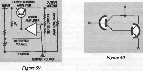
Figure 39, Figure 40
The inverters and converters are chopper sup plies, but, they usually use electronic oscillators in place of electromechanical vibrators.
Electromechanical vibrators and choppers are similar to the mechanism that operates door bells. Instead of a clapper that strikes the bell, the moving part is used for switching contacts.
RF Power Supplies
The RF power supply also utilizes Faraday's Law. A high- frequency oscillator supplies a rapidly changing current (and flux) to the primary winding. A high secondary voltage is the result. Except for the high voltages involved, the operation is similar to transformer sup plies operated from the 60-Hertz power lines.
The supply is a form of inverter if the output is AC, and, it is a form of converter if the out-put is DC.
CROWBAR PROTECTION
Serious damage can result from an excessively-high voltage delivered to an integrated circuit. Surge-limiting resistors or fuses will not protect the circuit because they are too slow. In other words, the damage is already done by the time they get into operation.
The crowbar circuit in Figure 38 is fast enough to protect most circuits. There are many variations of the circuit.
Diode X1 puts a positive voltage of about 0.7V on the cathode of SCR X 2. So, the DC supply voltage must be high enough to raise the gate above 0.7V before the SCR can con duct. The reason for keeping the cathode above the common voltage is so that noise signals and transient voltages will not accidentally kick the SCR into conduction. However, crow bar circuits may have the SCR cathode connected directly to common.
If the voltage across the load resistance goes above its rated value the gate of the SCR activates the crowbar circuit.
The conducting SCR puts an immediate short circuit across the power supply output. The resulting high short-circuit current may be used to blow the fuse or trip a circuit breaker.
So, check the crowbar circuit before replacing the fuse.
REVIEW AND ADDITIONAL NOTES ON TROUBLESHOOTING
Some of the theory and troubleshooting procedures will now be reviewed and extended.
Manufacturers sometimes supply troubleshooting flow charts that are designed to lead you through a maze of measurement steps. The troubleshooting material in this monograph should NOT be substituted for the manufacturer's procedures.
Experienced technicians will not agree with all of the techniques described here. Two technicians may troubleshoot a circuit in different ways that depend upon their choice of instruments and procedures.
I have made it a point to describe procedures that are safe and with the least possible damage to equipment. This monograph is a starting point if there is no manufacturer information available.
I have not incorporated speed into the procedure. That is best obtained with experience.
Always keep in mind the troubleshooting technique called the statistical method Experienced technicians know that there are certain components that are very likely to fail before others.
For example, the components that get hot during normal operation are often more likely to fail than other, cooler, components. The power amplifier in a regulator is a likely suspect. Be sure to check the power amplifier for emitter-to- collector shorts. That's a common problem.
If you are working on the same system most of the time you should keep notes on often encountered troubles. At a seminar conducted with technician members of the Kansas Electronics Association (KEA) there was unanimous agreement on the benefit of keeping a note book. The technicians record troubles in various systems.
Closed-loop regulators often require special procedures. The output voltage of the regulator depends upon the control input; and, the control input depends upon the output voltage.
If there is a problem anywhere in this closed loop it will cause changes in all of the other sections. In most cases it is useful to open that loop or defeat the loop. Then, troubleshoot the circuits one-at-a-time. See Figure 39. A bipolar transistor is a current-operated device. An increase in emitter-base current causes an increase in collector current; and, a decrease in collector current occurs when the emitter-base current decreases.
Even though the bipolar transistor is current operated, its operation is often described on the basis of voltage. The assumption is that an increasing or decreasing voltage corresponds to an increasing or decreasing current.
An SCR (and TRIAC) also operates on the basis of current. A gate current can produce an anode current if the proper cathode-to-anode voltage is present.
One disadvantage of current-operated amplifiers is that they require input-signal power [V x I] for their operation. In an analog regulator that means a decrease in operating efficiency.
There are voltage-operated, power-control devices that do not require much current on their signal input electrodes. An example is the VFET. Despite the obvious advantage of voltage- operated power control devices they have not been used extensively in regulator circuits at this time. That situation could change in the near future.
The Darlington amplifier of Figure 40 is a very popular power-control device in modem regulator systems. It has the advantage of being a power amplifier with a relatively high beta. Darlington amplifiers are usually put in the same case so their operating temperatures will be the same.
You could fill an encyclopedia with variations of the circuits I have discussed in this monograph.
For example, I gave the familiar 2-resistor and 3-resistor versions of the sense circuits. How ever, in switching supplies there is often a separate winding on the output transformer that is used to sense the output voltage.
The power "amplifier" in a switching supply is often a high-current SCR. Its low cost and ability to switch high-current pulses makes it a good choice for that job.
I gave the symbols for regulating transformers; but, I have seen many circuits with that type of transformer represented with a standard transformer symbol. You can't tell it is a regulating transformer unless you read the small print.
Stiff regulators make it possible to reduce the complexity of the filter circuit. For that reason, a high ripple content in the output voltage may indicate a defective regulator circuit rather than a filter problem.
A key feature of a startup circuit is a DC voltage obtained by rectifying the AC power.
That resulting DC voltage supplies the oscillator to get the switching regulator working. As soon as the DC output of the switching supply is obtained, the line-rectified DC is removed.
The series-pass power transistors discussed in this monograph were NPN types. Always be alert to the fact that a PNP transistor can be used for that job. (As mentioned before, you may also encounter an SCR used for power control.) Identifying the Types of Problems in System Supplies An article by Jim Smith of Sencore that appeared in Electronic Servicing & Technology magazine describes some of the difficulties in servicing power supplies that are an integral part of an electronic system. Here are the difficulties as described by Jim Smith.
First, it is tough to tell if there is really a problem or whether the fuse or circuit breaker is simply opening too soon.
Second, most problems cause the protective device to open as soon as the power is applied which makes it tough to make any circuit measurements. You can't just jumper across the fuse or circuit breaker without risking extensive damage to other components and circuits that are drawing too much power.
Third, it is often tough to tell whether the problem is in the power supply or the load connecting to the output.
By using an isolated AC power supply with current and voltage meters you can start applying power to the defective system starting with a low AC voltage and keeping your eye on the current. You know how much current should be allowed by the current rating of the fuse or circuit breaker. If the current starts to rise rapidly with a fixed rate of increase of voltage you know it is not just a premature tripping of the circuit breaker or blowing of the fuse.
The next step is to operate the equipment with a lower voltage (and especially a lower current) then use your voltmeter to troubleshoot the power supply and output circuitry.
You should never disconnect the sense lead in a regulator with the power supply energized! That would cause the supply to immediately try to recover. That, in turn, can cause a destructive overshoot.