Two designs with various circuit options
by D. C. Read, B.Sc.
------------
Performance
Signal-to-noise ratio:
Simple version 62dB at 1mV input
27dB at 1uV input
FET version offers an improvement for low signal levels of 1-100uV e.g. 55dB instead of 47dB at 10uV.
Distortion:
Simple version: 0.5% at 1kHz and 75kHz deviation (1mV), see text for method of improving to 0.1% FET version gives 0.12% at 1mV, 0.08% at 1uV.
Crosstalk:
34dB 80Hz to 5kHz with C28, R27 optimized.
RF performance: See part 2.
----------------
Among the many benefits conferred on the home constructor by the increasing sophistication of available packaged components is that these allow complex circuit ideas to be not just considered as expensive ideals but realised in practice with comparative ease and economy. This is particularly true in the field of FM stereo reception.
L. Nelson-Jones pointed the way in his articles. Further development of these ideas has led to a more comprehensive design, two versions of which are described below. For both, apart from the usual consideration of first-class performance and stability of operation, the main aim has been to eliminate time-consuming RF and IF alignment difficulties and the possible need for expensive test equipment. In the following description, modifications and optional extra facilities are discussed, and the necessary constructional details given (see also part 2).
The first, and simplest, version makes use of the well-proven Nelson-Jones IF and demodulator sections (though slightly modified) and replaces the discrete-component front end with a voltage-controlled tuner module. It also incorporates on the same board a phase-locked loop stereo decoder circuit based on the Motorola chip.
Pre-selected station change is by means of push-button switching with an extra switch position giving access to a manual control for tuning over a large part of Band II. Included in the design are regulator circuits for providing both the main supply rail and the constant-voltage source for tuning control.
The more advanced development uses an RCA CA3089E package containing IF amplifier/limiter and demodulator circuits which are sufficiently sensitive to allow all the IF pass-band shaping to be performed at a lower level: limiting starts with an input of about 15uV for the RCA integrated circuit. Thus, only a small amount of gain in the preceding stages is required, to make up for ceramic filter losses and provide impedance matching, and the 20dB gain i.e. (CA3053) used in the simple version is therefore not needed.
In addition to the composite signal output, the CA3089E produces:
- delayed AGC voltage
- push-pull current supply for AFC
- adjustable inter-station muting voltage.
- direct voltage proportional to the RF signal amplitude to actuate a tuning meter or show received field strength.
Of these, the first is most useful. It is used here to control the gain of an additional aerial-fed RF amplifier which, as well as giving the tuner increased sensitivity for reception of weak incoming signals, attenuates those of excessive strength to reduce the risk of local-oscillator pulling, an effect which can occur when the LP1186 module is over-driven. More particularly the AGC circuit using this control feed can easily be tailored to suit different reception conditions according to location and requirement.
In the simple version of the tuner, an AFC feed is conventionally derived from the demodulated audio and, because of other precautions taken against drift, is more than adequate for all practical purposes. The availability or a separate AFC supply is not therefore particularly significant except that it does more readily offer a choice of control sensitivity. Similarly, the other two CA3089E outputs have only limited application in the present design. For general household use muting is not required with stable push-button tuning; neither is there need to inspect the incoming signal level. These, optional facilities are included only to allow for band-searching by manual tuning.
The decoder, stabilizer and tuning-voltage circuits are the same in both versions of the tuner.
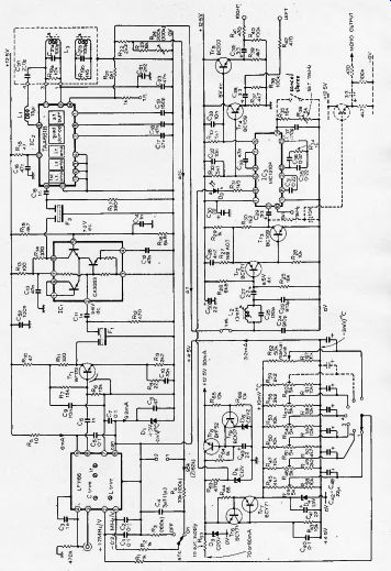
Fig. 1. Simpler version of tuner design using LP1186 module. Stereo decoder
and tuning circuits are common to the two tuner designs. See part 2 (April
issue) for modification for Toko module. Station selection switch should have
break-before-make contacts. Resistors can be 5% high stability or metal film
types, rated at 1/4 watt. Capacitors are 2% polystyrene types for signal circuits,
disc ceramics for RF decoupling, and tantalum types for audio coupling and
decoupling. Switch shown with broken lines is closed for mono reception to
kill 76kHz oscillation. Values in parentheses are for lower AFC sensitivity.
Simple version
The LP1186 module circuit is "floating", but is made unbalanced by (Fig. 1) so that it is suitable for connection to the aerial via a 75-ohm coaxial feeder. A.C. earthing is used because the module negative supply rail and the metal cover is held at about +4.5 volts with respect to the main chassis earth by zener diode D1. There are two reasons for this, first, the LPUS6 requires an 8 volt supply, instead of 12.5 volts nominal as in the remainder of the tuner circuit. And second, the local-oscillator frequency-control circuit operates about a 0-volt zero error signal at pin 1 (ref, pin 8) but the AFC voltage produced by the TAA661B has an on-tune center value of around 5.4 volts, reduced to about 4.5 volts, in the chain R22, R23 and R24.
A minimum incoming RF signal of about 2 uV RMS for 30dB quieting is necessary to give adequate limiting in the TAA661B amplifiers; and a maximum amplitude of between 5 and 10mV is recommended to prevent oscillator pulling.
The remaining LPI186 module at pin 2 is the tuning control voltage from the push-button selector circuit which has selected values between 4.7 volts and 6' volts; a somewhat greater range is provided in the continuously-variable manual tune position. Both this voltage feed and the AFC line are decoupled (R1/C1, R2/C2) to prevent spurious modulation effects which could be caused by hum fields or other stray signals picked up on wiring to and from switches, AFC sensitivity Following normal practice, of course, the AFC feed passes through components, C4, R4l which filter out the audio modulation. The input resistance at pin 1 of the LP1186 is 62 kOhm, if R4 has the value 100k-Ohm in Fig. 1, the useful AFC voltage change is about one-third of the total available. If greater sensitivity is required, therefore, the value of R4 must be reduced and that of C4 raised to maintain effective audio rejection. A suggested pair of values is 33 kOhm and 3.3uF. With these in circuit a 50% increase in sensitivity is achieved but at a greater risk of locking to an adjacent station.
The problem of incorrect selection because of excessive AFC is aggravated by the interleaving allotment of transmitter frequencies and therefore mis-selection is most likely to occur at points where interleaved channels are received at comparable strengths. A typical instance might be a location midway between the Oxford and Wrotham transmitters which radiate basically the same Radio 1, 2 and 3 programs on interleaved frequencies. In such circumstances, the station chosen by the receiver might not be the wanted one; the choice will arbitrarily depend on the direction of tuning change. As the tuning shifts up or down the band from one selection to the next, the local oscillator might be captured by an in-between transmission which creates a large enough AFC voltage to make it lock to this station in error. Over-sensitivity of the AFC can also result in station-jumping effects where the receiver suddenly changes tuning and switches away from one transmission to some other because of a reduction in received signal strength; aircraft flutter, particularly, causes such mis-operation.
It is obviously good practice then to set the AFC sensitivity so that it is no more than just sufficient. In the event that particular reception conditions are such that sensitivity is already too large, even with the circuit as given in Fig. 1, two pairs of diodes in series (types 1N914 and 1N916 are suitable) can be connected back-to-back across at the LP1186 AFC input. With this modification, the frequency-control swing is limited to less than the 300kHz station spacing and thus station jumping or mis-selection will be prevented.
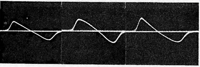
Fig. 2. Effect of changing dummy circuit resonance on transfer slope of demodulator,
(a) left, optimum setting (b) middle, upper core "in" on optimum
setting (c) right, upper core "out" on optimum setting. (1 V/cm.)
The 10.7 MHz output from across pins 6 and 7 is fed to Tr1 which provides the correct source impedance for the first ceramic filter, and also gives some amplification. The amount of gain is set by the value for Rg and should be such that, for a low RF input of 10pV to the tuner, a suitable signal level (say 10mV) is available to drive the first IF amplifier in the demodulator module; this gives 40dB quieting. A 20dB amplifier stage comprising the cascode-connected circuit in 1C provides the correct source impedance for F2 which finally passes the band-shaped IF signal to IC2.
Remember that the Vernitron type FM4 components used for F1 and F2 must have the same colour marking.
The green-coded type is recommended because these have a pass band centered on 10.7MHz and therefore match the curve normally provided by the maker's preset adjustment of LP1186 modules, if ceramic filters of another colour code are used, it may be advantageous to re-tune the two output band-pass coils in the LP1186 for optimum performance, These are accessible through holes in the module cover. The best way of making the adjustments is to use a frequency-sweep input signal displayed on an oscilloscope connected across the demodulator input (pin 6 of the TAA661B), Such ideal methods are rarely available to the home constructor, however, and the practical compromise is to select a weak incoming signal and then adjust the coils for least background noise in the sound output from the tuner.
For reception of weak signals it may be worthwhile to carry optimization of the LP1186 one step further and adjust its input circuit to match the aerial. Two other holes in the LP1186 cover allow separate access to the aerial trimming coil and its associated capacitor. Because these components affect opposite ends of the tuning range, their adjustment is a relatively simple matter: using the manual tuning control, select a weak station radiating in the 87-89 MHz range and tune the coil for minimum noise; no more than a fraction of a turn is needed to show either that a reduction in noise is possible or that the optimum setting already exists. Change to a weak signal towards the other end of the band (96-97 MHz) and similarly adjust the trimmer capacitor. This is not an essential adjustment and will, at best, give only small improvement for weak stations.
Quadrature demodulator
The circuit surrounding IC2 shows two main differences compared with that in the original Nelson-Jones tuner. First, the IF signal sample used to derive the quadrature-phase demodulating signal is taken through an inductor L, instead of a capacitor (note that C21) in Fig, 1 is now simply a DC blocking component). This is done so that the resulting demodulator transfer slope is in the correct sense for AFC Second, the phase-shifted carrier itself can optionally be produced by two tuned circuits with twin coils L3 having separate cores but mounted on the same former. As Fig. 1 shows, one of these circuits is a dummy, the tuning of which is adjusted so that the modifying component of current induced in the main tuned circuit is of suitable phase and amplitude to give a straighter transfer slope. The effect of changing the dummy circuit resonance is illustrated by the three sweep photographs which show: (a) the transfer slope for an optimum setting; (b) and (c) non-linearity resulting from two incorrect settings.
There is, unfortunately, a difficulty to be met in using this apparently simple and cheap modification; it is only effective if properly adjusted and although adjustment is relatively easy, it necessarily entails the use of extra test equipment. Further, the basic reduction in tuner output distortion is marginal (typically, 0.5% total harmonic content for the one-coil circuit; 0.1% with two coils) and would be hard to detect aurally. Even so, a low level of harmonics in the demodulated signal, helps to prevent intermodulation products in the overall stereo decoding process and, provided that suitable test equipment is available, the additional circuit and set-up procedure offers a worthwhile advantage.
There are two possible methods of adjustment. The first uses a distortion meter to measure the total harmonic content in the audio output (taken via a L5kHz low-pass filter such as that described later) for an RF tuner input modulated by 1kHz at ± 75kHz deviation, The filter is needed here to reject the 19kHz pilot tone as well as the 23kHz transmitter switching signal remaining in the audio output. The dummy tuned circuit (upper core) is then simply adjusted to give a minimum reading on the meter. However, since the distortion figure which can be achieved is low (about 0.1%), the exact null point may be somewhat masked by noise. The alternative method overcomes this. It uses a wave analyzers tuned to the 3rd harmonic of the incoming 1kHz modulation which is again at the maximum deviation of ± 75kHz; in this instance there is no requirement for a low-pass filter. The adjustment of dummy circuit tuning is made for a minimum output at 3kHz.
The demodulated multiplex signal from pin 14 of IC2 at about 0.5 volts RMS for ± 75kHz incoming FM deviation has a DC component of about + 5.4 volts for the in-tune condition, in fact, the value given here is a nominal one and varies between different examples of the TAA661B; since this varying direct voltage is used to operate the AFC circuit and must be matched to the supply offset provided by D1 (4.3 volt zener), variable resistor R24 is included in the AFC potentiometer chain to allow fine adjustment.
The method suggested for adjustment is as follows. Switch AFc, off. Using the manual control, set the tuner well away from any station, i.e. completely off-tune. Measure the direct voltage at the IC2 pin 14 test point (this connects with the demodulator output via a protecting 1-kO stand-off resistor); normally, the value obtained will be about 5.4 volts positive.
Tune through a reasonably strong incoming signal and, by observing the voltage change from maximum positive to maximum negative (a total peak-to-peak swing of, say, between 2.5 and 3,5 volts) sample the S curve to find the on-tune point, which is at a voltage nearly equal to that already established for the off-tune condition. With the tuning set at this point, transfer the meter to the tuning-indicator connection points marked 1 and 2 in Fig.1. In the on-tune condition and with set at a maximum, terminal 1 will be positive with respect to 2. Adjust R24 to bring this potential difference to zero.
Switch AFC on and observe the possible slight change of meter reading. Again adjust R24 to restore it to zero. Finally, check the voltage appearing at the test point and operate the AFC switch to ensure that this voltage remains unchanged with and without AFC applied.
Tuning voltage selector circuit
The circuit used to provide a selection of pre-set direct voltages for tuning purposes in the LP1186 module forms the lower left of Fig. 1; this part of the circuit also includes the main supply voltage stabilizer.
All the tuning voltages are derived as proportions of a fixed voltage from zener diode D4 which is supplied with a constant current by the stabilizer circuit of Tr6 and Tr7. b4 is returned to 0 volts instead of the 4.5 volt rail used by the LP1186 module and the rest of the tuning voltage circuit, so of the 13-volt reference potential provided by D3, only about 8.5 volts is used for tuning. The main reason for this arrangement is that by allowing for a greater reference voltage than necessary, the zener diode used to provide it has a positive temperature coefficient large enough to give the degree of frequency-drift correction required. The coefficient of a suitable lower-value zener, although still positive, would be too small for this purpose; the figures for comparison here are +10.5mV/degree C for 64 and -10kHz/ degrees C for the oscillator.
Thus, with D4 connected as shown, the variation of control voltage with temperature has an effect on the tuning frequency which both opposes and, after accounting for potentiometer action and the 4.3 volt zener offset in the selector circuit as well as the tuning-voltage/frequency relationship, is about equal to the variation caused by a similar temperature change on the local oscillator itself. Obviously, for automatic compensation to become fully effective, the relevant components in the tuner must themselves have reached their normal working temperature.
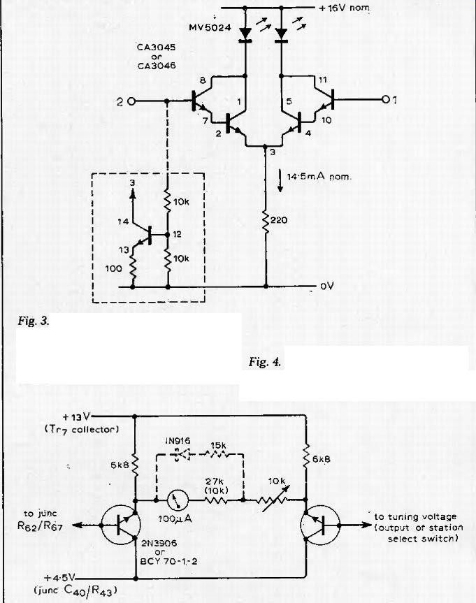
Fig. 3. in this tuning indicator option, the 220ohm resistor can be replaced
with the circuit shown in broken box to ensure equal lamp brightness either
side of tuning position.
Fig. 4. Optional meter circuit provides tuning scale for manual tuning. Meter is RS Component MR100.
If the number of pre-selected stations required is more than, say, 12 then as each chain takes about 0.4mA the total drain on D4 might be greater than its reserve of current and it would no longer be effective in maintaining a constant voltage. In this event, it will be necessary to increase the current supply from Tr7 by reducing R44 to the next lowest preferred value (56 ohm). Transistor Tr8 and Tp9 form the main parts of a conventional series regulator acting with reference to zener diode D,; to provide the main supply rail of 12.5 volts from the nominal 16 volt DC input.
An incoming feed of this value is conveniently obtained by peak rectification of the output from a mains-to-12 volt transformer. It should be capable of supplying at least 250 mA RMS at 12 volts to ensure the required rail voltage.
The 12 volt zener, D5, provides a reserve of current for supplying the stereo indicator D, so that the main supply rail is not affected by current changes as this LED is switched on and off.
Stereo decoder and output circuit
The right hand of Fig. 1 shows the decoder module feeding twin audio output circuits and preceded by a low-pass filter mainly comprising L2This filter passes the composite multiplex signal obtained from the demodulator including the upper subcarrier sideband extending to 53 kHz but rejects frequency components outside this range. Ideally, the filter should have a flat pass-band with negligible phase distortion so that the mono and stereo information channels occupying 0 to 15 kHz and 23 to 25 kHz, respectively, can be recovered with equal fidelity. It should also cut off sharply to give the maximum possible attenuation to all signals outside this band, especially in the range 99 to 129 kHz, which includes the first odd harmonic of the stereo channel subcarrier with sidebands.
To satisfy such a requirement would entail the use of a complex network; in practice, the simple, single-section filter used in the tuner is adequate, even more so if the demodulator dummy tuned circuit, discussed earlier, is used to reduce the level of interfering harmonic components. As an added refinement, the tuning of L2 can, if desired, be adjusted to set the first rejection frequency so that optimum separation is obtained for signals in the region of 5kHz; this is the upper end of the audio range over which good stereo separation is most important.
Further overall response adjustment is given by the feedback stage of Tr2/Tr3. The C28, R27 circuit causes a basic 6dB/octave rise which is modified by R2S| so that the resulting slope counteracts a general slight fall in the preceding circuits. As before, equality of level for both the mono and stereo information channels at the decoder input is the criterion. The low output impedance presented by Tr2/Tr3 is a necessary factor in the proper operation of the MC1310P circuit; separation at the lower end of the audio band suffers if this requirement is not met.
The decoder module, IC3, is operated in a normal manner with surrounding circuit values much the same as in an article which introduced the MC1310P (Wireless World July 1972). The only addition is the optional 76 kHz oscillator-disabling switch shown in Fig. 1. If fitted, this is used to inhibit stereo operation for exceptionally weak incoming signals when the resulting 20dB improvement in signal to noise ratio offers a worthwhile advantage.
De-emphasis of the decoded audio signals taken from open collectors at pins 4 and 5 of the MC1310P is arranged by shunting each of the load resistors, R32 and R33 with 0.01uF capacitors. The twin output signals are then available from buffer emitter followers, Tr4 and Tr5. Apart from the more obvious benefits of having low-impedance outputs, these are particularly useful, with series resistors R41 and R42 suitably changed in value, for feeding the 15 kHz low-pass filters (part 2) which may be inserted between the tuner and its following amplifiers.
Extra circuits
Where stereo programs are to be used to make mono recordings, the emitter-follower circuit shown dotted in the lower right hand corner of Fig. 1 would be a useful addition. This simply provides a low-impedance output of the separately de-emphasized multiplex signal.
Another possible extra facility is the tuning indicator circuit illustrated by Fig.3. This basically comprises two Darlington pairs in a single i.e. with a common-emitter load and light-emitting diodes in the collector feeds. When connected to AFC circuit points 1 and 2 in Fig.1 , these diodes show equal illumination for equal input voltages at pins 6 and 9 to indicate the in-tune condition whereas one or other is brighter on either side of this point. An optional refinement to the basic Fig.4 circuit (shown boxed) overcomes possible asymmetry in individual diode brightness for off-tune conditions. As the modification shows, the common-emitter resistor is replaced by a constant-current source using a spare transistor in the i.e. and two additional resistors.
As a further aid to station selection, the reader may like to include the circuit shown in Fig.4 and thus provide a tuning-scale facility. The added circuit mainly uses a readily-available and reasonably cheap edgewise meter which in my installation is mounted together with the pre-selection buttons and other controls on a remote front panel. Fig.4 shows how the meter is connected into the main tuning/selection system detailed in the Fig.1 circuit which requires only two small modifications. One is the addition of a series resistor between R62 the manual tune control, and the 11-volt maintained tuning-voltage supply rail. The value of the added component (typically 18 kOhm) is chosen on test so that the meter full-scale deflection (indicating 98 MHz) occurs at the fully-clockwise slider setting of R62. Second, the value of RG7 will need changing to, say, 22 kOhm to make the R62 fully-anticlockwise setting coincide with a tuning frequency of 88 MHz. The values actually required might be different because the tuning-voltage spread for the LP1186 varies by about 1 volt at the low end of Band 11 and about 3 volts at the top end.
With the meter circuit as shown full line in Fig. 4 the scale (constructed by experiment) will be cramped at the low-frequency end. This is an advantage if all the pre selected station frequencies are here, because the more open upper-end markings then give better accuracy when exploring/setting in the manual tune position. However, in some other instance it may be necessary to make the scale marking more linear and this can be done by modifying the meter circuit as shown dotted in Fig.4 whereby the scale already provided with the meter can conveniently used such that 0 = 88 MHz and 10 = 98 MHz.
Improved performance; further facilities
by D. C. Read, B.Sc.
----------
• The simpler version described in part 1 comprises tried and trusted circuits, up-dated with refinements intended to make construction, line-up and operation easy; stability and utility are the essential features. The overall design is flexible, and various special facilities can easily be added either during or subsequent to the main construction. These extras include:
-a twin tuned-circuit demodulator which reduces harmonics in the recovered multiplex signal but which needs proper adjustment using a wave analyzer or distortion meter
-a stereo-inhibit switch which allows mono reception of weak stereo signals thus giving a 20dB improvement in signal-to-noise
-a buffered and de-emphasized mono feed derived before decoding and intended for tape-recording
-low-pass audio filters to remove unwanted components from the tuner outputs, useful for tape recording either stereo or mono
-a tuning-indicator circuit.
• The more advanced tuner can be provided with any or all of the additions listed above; it also shows further refinements, some optional, which give improved performance in certain respects but which increase the number of necessary adjustments both in setting up the tuner and in its normal operation.
These modifications and additions are;
-an extra gain-controlled RF stage giving increased sensitivity and stability, and improved signal-to-noise performance. The design of this stage also allows different AGC characteristics to be chosen either as a result of fixed circuit changes or subsequently by adjustment of a panel control to suit various reception conditions
-a more comprehensive AFC
system which, like the AGC
circuit, can be varied in its effect under external control (Rg could be a front-panel variable resistor)
-a received signal-strength meter circuit with calibration curve.
This meter feed could also be used for stereo-threshold switching.
-adjustable inter-station muting.
------------
Changes which provide the tuner described in part 1 of this article with some additional control and monitoring facilities and a more flexible input circuit are shown in Fig. 5. The extra gain-controlled RF stage comprising the dual-gate MOSFET, Tr1, can be arranged to function in different ways according to local reception conditions.
Two alternatives are illustrated in the circuit diagram by the indicated possible connection of a 10-kOhm resistor between Tr1 source and the positive supply rail. Circuit operation is as follows.
With 10kOhm resistor. The stage produces either a gain (maximum 6dB) or a loss (maximum 12dB) under the control of the AGC voltage returned from the i.e. This division into two control regions makes the most efficient use of the available 18dB AGC range whereby large incoming signals are reduced in level to prevent oscillator pulling but weak signals are given low-noise amplification before the LRU86 RF and mixer stages, so that the noise these produce is added in smaller proportion.
Without resistor. The stage gives low-noise gain with a value between zero and 12dB again depending on the AGC voltage. This arrangement is suitable for tuners used in fringe areas where received signals are low; i.e. where increased sensitivity is required and high-level incoming signals are not normally encountered.
A further possibility makes even more effective use of the MOSFET characteristics but at the expense of added complexity, particularly in setting up. If the Tr10 source is held at a fixed voltage, say by means of a low-value zener between it and the 0-volt rail with a current feed via a resistor to the positive rail, then the AGC range is extended because the source-follower feedback action which modifies the effect of the control voltage on gate 2 is inhibited.
The spread of characteristics for FET devices is such that, without this stabilizing feedback, the bias on gate 1 needs preset adjustment to give maximum gain for weak signals. In practice the required bias is easily set by connecting gate L actually the earthy end of the input coil, to a variable tapping in a high-resistance potentiometer chain across the zener. Then, with the AGC voltage on gate 2 at its most positive value, the bias is varied until the highest possible stage gain is obtained. The likely performance of such a circuit is a maximum gain of 16dB and a control range of 25 to 30dB. The circuit which includes the LP1186 module and the impedance-matching stage, Tr2 is largely as in the simpler version, the only difference being an additional resistor in the AFC feed. The choice of value for this component, which determines AFC sensitivity, is dictated by local reception' conditions.
High sensitivity is given with the value at 47k-Ohm as shown in Fig. 5. If equal-strength neighboring-channel signals are present, the degree of control might be too great such that the tuner could be captured by an unwanted station as the local oscillator sweeps through the relevant frequency while changing to select the wanted station. If this occurs, reduce the resistor value, possibly to as low as 5k-Ohm, which still allows a useful amount of control.
Because of the extra gain now available at the tuner front end and also in the CA3089E module, the IF amplifier IC2 is not required and the correct impedance for F2 is provided instead by a grounded-base stage, Tr3.
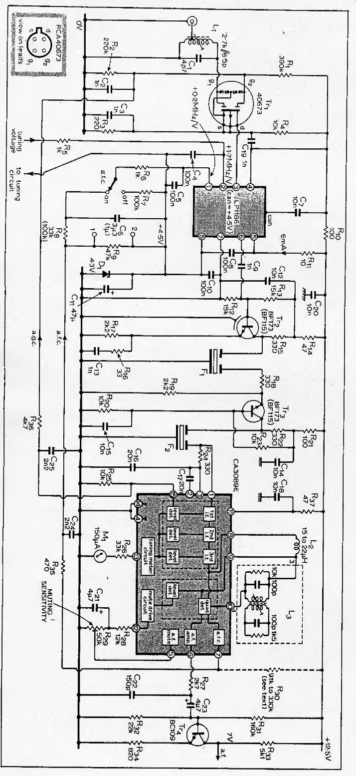
Fig. 5. Improved performance at low signal levels is obtained with this circuit,
which uses the tuning and decoder circuits of Fig. 1. Sequence of connections
for Tr2 is b, e, c, screen (on-lead view). On the CA3089E pin 8 corresponds
with the tag location.
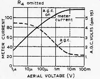
Fig. 6. Curves showing AGC performance and meter current, taken with R4 omitted.
Delayed AGC voltage is at pin 15 on CA3089E.
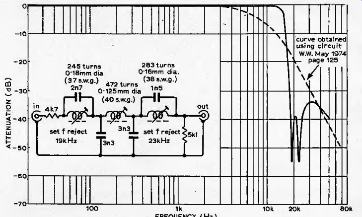
Fig. 7. Double notch output filter option.
Inductors wound on 14mm Mullard Vinkor assembly, with Ferrox core violet type LA1228. Filter, which has a 6dB loss, should have 25k-Ohm load.
Although the RCA limiter/demodulator circuit is more complex than its TAA661B counterpart it operates in a similar manner, using an inductive carrier feed to obtain the quadrature reference phase and has the optional dummy tuned circuit to improve linearity of the transfer slope. The external circuit differences mainly concern the use of additional facilities provided by the IC. Because the AFC signal is derived from a push-pull, open-collector current source in the CA3089E circuit, it is possible that the equal and opposite current condition in a given sample of the i.e. does not occur precisely at the middle of the demodulator S curve. In such a circumstance, a small correcting bias can be provided through a resistor with a value in the 91 to 330kOhm range, connected either to the positive rail, as shown, or to 0 volts, whichever is appropriate. To find the required value and the appropriate supply connection point for this resistor, a method similar to that already described for matching the AFC offset voltage in the simple tuner is suggested; in this instance, however, the S curve is sampled by measuring the voltage across the 150pF capacitor in the pin 6 output circuit.
The completely off-tune condition is used to find the particular voltage value which represents the effective S curve center and this is then established by tuning to a strong station. Now connect the meter across the AFC sensitivity-controlling resistor, R9 (points 1 and 2). With the AFC switch off, vary the bias to pin 7 until the measured voltage is zero and remains so with the AFC on. (Note that, as the AFC drive is from a constant-current source, there is automatic compensation for the supply voltage --offset at pin 8 of the LP1186.)
The varying voltage output from pin 13, shown as the meter current curve in Fig. 6, is not used in this tuner for stereo threshold switching. It can, however, be fed to a suitable meter circuit to give a received-signal strength measurement by relating the indicated current to the calibration curve shown in Fig. 6.
Setting of the audio muting sensitivity control is done by tuning manually through a number of stations and increasing sensitivity until the noise between these is reduced to a minimum.
The demodulated multiplex signal, at about 140mV RMS for ± 75kHz incoming-signal deviation, is fed via Tr4 to the 50kHz low-pass filter, decoder and audio output circuits, already described.
An extra stage around Tr4 provides a small amount of gain to compensate for the lower output from the CA3089E demodulator and presents the correct source impedance to the filter.
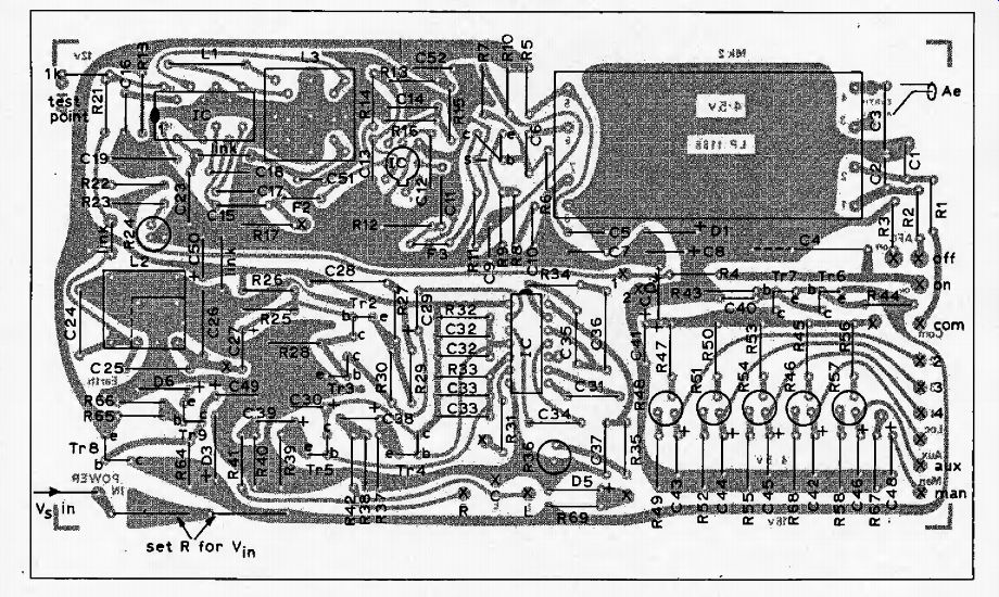
------ Component location and p.c. board layout for Fig. 1.
Optional 15kHz low-pass filter
The output signals from the tuner contain components at the pilot-tone frequency and the switching frequency.
Apart from producing noise, these unwanted signals can cause difficulty when the tuner stereo output is tape-recorded. If the recording bias beats with one or other of the out-of-band components, or more probably, with their harmonics, then the product frequency could be within the audio band and the resulting signal would produce interference. Such undesirable effects can be prevented by including a low-pass filter in each of the output circuits.
The audio band transmitted is limited to 15kHz, as a necessary factor in normal pulse-code-modulated signal distribution, so it is reasonable to use a sharp filter cut-off at a frequency just above 15kHz. The circuit of a suitable filter is given in Fig. 7 together with its response. The second notch, at 23kHz, is at the frequency allotted to a control signal which the BBC uses for distribution-route and transmitter switching.
(An active filter would have required a more extensive circuit requiring many more components to achieve the high rates of response change at cut-off and the notch sides.)
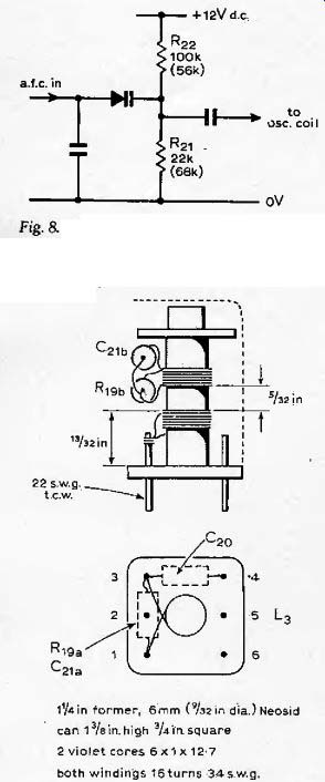
Fig. 8. If Toko EF5600U-1 module is used in place of LP1186 change values
of resistors in Toko module to those shown in brackets. L3 component numbers
above as for Fig. 1. Capacitor marked C20 is omitted in Fig. 5. Simpler coil
uses 10 turns on Neosid E3 assembly. Phase shift coil is a Sigma SCW screened
RF choke, or Painton equivalent. L2 Fig. 1 is wound on a Milliard Vinkor assembly
with 14mm violet core and 172 turns of 38s.w.g. enameled wire. L, in Fig. 5
is 8 1/4 turns, tapped at 1 1/4 turns, on Neosid 6mm former with 22s.w.g. wire.
---------- Front panel and controls can be mounted remote from the printed
board.
Tuner RF and IF performance
The four most important figures here are those for IF and image rejection, which relate to operation in the RF section, and for AM and adjacent/alternate channel rejection given by the IF circuits.
The first two depend on RF circuit selectivity and in both versions are determined by the performance of the Mullard LP1186 module. The specification for this quotes an IF rejection of 65 dB for 95MHz input and an image rejection of 40 dB. If better RF performance is required, this can be easily obtained but at increased cost by replacing the LP1186 with the Toko type EF5600U-I tuner module which contains four varicap-controlled tuned circuits and has image and IF rejection figures both quoted as 90 dB. A module of this type has been successfully fitted to the author's tuner with some small modifications, as below.
Fitting Toko front-end
Change of tuning voltages. For tuners operated in the London area, the necessary changes to pre-set tuning voltages for stations at the ends of the band are:
---
LP 1186 EF5600U-1 (w.r.t. pin 8) (w.r.t. 0V) 89.1 MHz (Radio 2) 2.4V 3.5V 97.3 MHz (LBC) 6.0V 7.5V
Change of DC offset and AFC center-voltage. The EF5600U-1 tuning voltages are referred to 0 volts instead of the +4.5-volt offset present at pin 8 of the LP1186. This difference necessitates two modifications. First, the 4.3-volt zener, marked Dl in both diagrams, must be replaced with a shorting link. Second, in the Toko module, the maker's circuit diagram shows that the AFC circuit involves a separate diode with a 2-volt bias obtained from resistors numbered R21 and R22 as illustrated in Fig. 8. Because this circuit is intended for operation with an incoming AFC signal centered on 0 volts, it must be modified to suit the +4.5-volt center value which obtains in the tuners. The suggested changes are marked in parentheses in Fig. 8, giving an offset of about 6.5 volts.
The figures for AM rejection, quoted from the manufacturers' data for 30% AM, are -45dB for the SGS TAA661B and -55dB for the RCA 3089E. Performance in respect of adjacent/alternate channel rejection is determined by the IF pass-band response characteristic which, for both tuner versions, is the resultant of two FM-4 ceramic filters in cascade. These components were also used by Nelson-Jones, and a curve showing the insertion loss for the combination appears in his original article. This gives the 3dB-down bandwidth as ±110 kHz, and off-tune loss figures of 40 dB at ±200 kHz and 60 dB at ±280 kHz. Rejection of unwanted channels is thus more than adequate..
Further details of construction and alignment
by D. C. Read, B.Sc.
As the result of experience gained in building what might be termed production models of the FM tuners described recently in Wireless World (March and April), the following information on construction and alignment is given, together with suggestions for possible modifications and component alternatives, and some corrections to details already published.
As a board layout was arranged to take specific capacitor types, further details are:
C1, C6, C15 --polystyrene 2 percent types were used originally but disc ceramic capacitors are also suitable;
C20, C21a, C21b --polystyrene;
C24, C25. C26 --polystyrene (these low-pass filter components need to be as accurate in value as possible);
C4, C32, C33 --10 percent polyester, e.g. Mullard type 334.
On the p.c. board supplied for the tuner there are two positions marked for each of C32 aid C33. This provides for additional components to be installed so that the theoretical 75uS de-emphasis time-constant can be obtained very accurately if necessary. Unless otherwise specified, the remaining capacitors are either disc ceramic or tantalum types, the last-mentioned being marked with polarity on the circuit diagrams.
Push-button assemblies
Push-button switch assemblies may be used, but remember that as these are generally equipped with high-value adjustment resistors (100kf2 per section), the reservoir capacitors, to C48 in Fig. 1, would not then be suitable because tantalum capacitors are subject to considerable variation of leakage current with change in temperature.
They are unsuitable for use in a high-resistance circuit within an AFC loop; given a modest change in temperature, the resulting frequency bias created by the consequent change in the tantalum characteristics could so offset the AFC system as to prevent it giving satisfactory overall control.
As a compromise, disc ceramic capacitors of, say, 220nF could be used in these positions to provide a small but useful reservoir effect. Note, however, that without the decoupling action of the 22uF components, the tuning-voltage feed to the LP1186 module is more liable to pick up hum and noise interference and hence allow spurious modulation of the received signal. Thus, if a push-button unit remote from the tuner is installed, it is good practice to screen this feed and/or ensure that it is kept well away from possible sources of interference, e.g. mains wiring. When loaded with the high-resistance selection circuit, the tuning voltage regulator diode, D4, may be fed with much more current than is needed to carry out its control function. In this event, R44 could be increased, say to 1000. AFC circuit In Fig. 5 (April issue) a 3.3uF capacitor was specified for C6 in the AFC line from pin 7 of the CA3089E demodulator. This is an unnecessarily large value because the feed only carries an appreciable audio component under off-tune conditions. A smaller, and hence cheaper, component, say a 470nF disc ceramic or polyester capacitor, would suffice.
Too large an AFC range can be a disadvantage because of station-jumping. If four diodes, arranged as two series pairs connected back-to-back in parallel, are placed across points i and 2 in the AFC circuit, the positive and negative voltage excursions are limited each to about 1.2 volts so that the maximum possible tuning frequency change under AFC action is always less than the minimum channel separation.
The other modification concerns extension of the AFC sensitivity control as a front panel facility. This can be done by making a variable component, still connected between points 1 and 2, but with Rs taken to the slider. Such an arrangement then enables reduction in sensitivity to be carried out manually whenever necessary but does not prevent the voltage changes appearing across R9 from being used to operate the LED indicator circuit detailed in Fig. 4 of the March issue.
Muting circuit
In at least one of the advanced tuners so far built and aligned, the CA3089E muting output from pin 12 took the form of amplitude-clipped noise instead of varying DC
The interconnecting circuit feeding the muting input on pin 5 then produced an average of this output which was not sufficient to operate the mute when required. As the i.e. gave a satisfactory performance in all other respects, it was worthwhile making a suitable circuit change to correct for the abnormality. The circuit published in the April issue was therefore modified to give an increased output by disconnecting the existing circuit between pins 12 and 5 and connecting a 1N914 and 50kf2 potentiometer in series between pins 12 and 5 (anode to pin 12). Connect C21 between pin 5 and the zero-volt line.
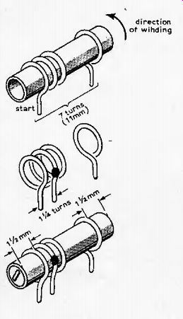
Aerial coil
The aerial coil, L1, used to feed incoming signal to the tuned RF stage in the advanced version is constructed as shown below. Note that the total number of turns on this coil is 7, not 8l A as stated on page 50 of the April issue.
Cut Neosid 6mm former to about 14mm.
Wind on 7 turns 22 s.w.g. tinned copper wire, equally spaced out to 11mm.
Remove former, tap at I'A turn from start, open turns adjacent to tap to avoid shorting.
Re-insert former and centralize. Screw in core together with p.t.f.e. tape. Coat with Denfix or nail varnish.
In some examples of the advanced version, C1 may not be required because stray capacitance and the input capacitance of Tr1 added together are sufficient
---------
Ceramic filters
Difficulty has recently been found in obtaining the Vernitron filters specified for F1 and F2 in both versions. Fortunately, ceramic filters from the Toko type CFSA 10.7 range are readily available.
These replacement components offer a performance which is not quite as good as that of the Vernitron FM4, but it is generally adequate for the tuners described. The Toko units are also cheaper --about half the cost.
If these alternative filters are used, a small change in Fig. 1 circuit values would be required because the amount of overall phase response correction given by C2S and R27 in the Tr2/Tr3 amplifier is no longer suitable. The values should be changed to 3.3nF and 2.4kOhm. Resistor R27 can be adjusted on test to obtain up to 38dB channel separation from 1 to 5kHz.
Adjustment of L3
The quadrature-phase signal derived for both demodulators, TAA661B in the simple version and CA3089E in the advanced version, could optionally be produced by means of a double-tuned coil at L3. When setting the two cores of L3 so as to take the best possible advantage of the linearizing effect of current in the dummy coil, it is essential that the cores be kept as far apart as possible in the former, thus minimizing changes in coupling between the coils when adjustment is made. The lower core is used to tune the mail L3 coil; it should initially be screwed in just enough to give as symmetrical an S-curve as possible. When this has been set satisfactorily, the upper core is added and screwed in enough to straighten the bend in the transfer slope as in the left hand trace of Fig, 2. More precise adjustment would require the use of a wave analyzer or distortion meter.