1 -- Circuits and operation
by J. A. Skingley and N, C. Thompson Ptessey Components Ltd, Swindon
Using a ready-made front-end, integrated circuits and. only one inductor, this tuner design is simple to operate, construct and set up. It includes novel circuitry to give inter-station muting, AFC restricted to less than station spacing, a single-lamp tuning indicator, temperature-compensated varicap tuning allowing stations to foe preset, and a linear-scale frequency meter. A simple stereo decoder circuit (part 2) uses active filters to eliminate "birdies" and remove subcarrier harmonics. Printed circuit wiring diagrams, assembly instructions and setting up procedure will appear in part 2.
The designer of technical equipment for the domestic market faces a problem. On the one hand the technical operating requirements can dictate a multiplicity of controls and demand a detailed knowledge of their use. On the other hand the operation must be simple and easily understood by people of all walks of life and professions. This design had to cater for non-technical people and children.
The first requirement then was that the system used should mask the technicalities and present the user with the simplest possible mode of operation, relying at most on traditional skills learned from more conventional AM receivers, without sacrificing the advantages to be had from a modem FM tuner.
The second requirement was to provide a tuner which was at least as good as the best commercial unit on ail technical parameters. The total design objectives were therefore:
requirement 1--ease of operation:
(a) provision for push-button tuning
(b) no undesirable outputs
(c) powerful AFC
(d) sensitive, unambiguous tuning indication
requirement 2-good performance:
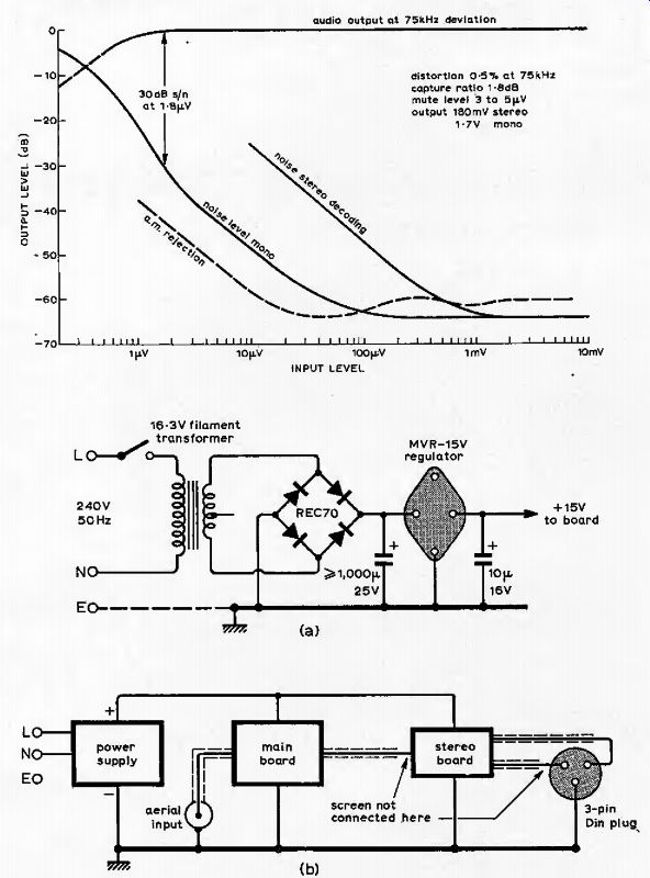
(a) 2uV for 30-dB signal-to-noise ratio
(b) 3-dB limiting 0,5pV
(c) image rejection 40dB
(d) IF rejection 65dB
(e) capture ratio 2dB
(f) AM rejection 60dB
(g) AF response ± 1dB, 20Hz to 15kHz.
The combination of these objectives led to a system which to our knowledge is unique (Fig. 1).
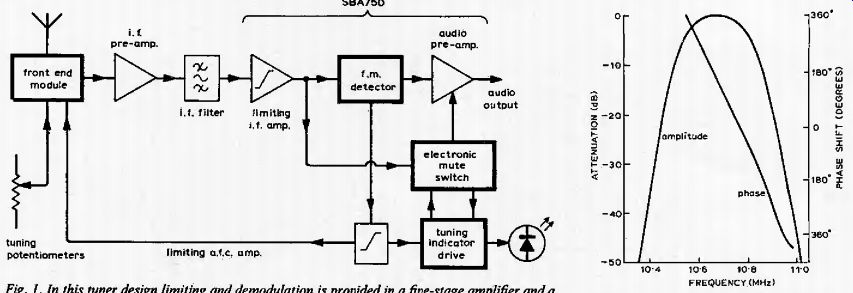
Fig. 1--In this tuner design limiting and demodulation is provided in a five-stage amplifier and a balanced demodulator, both in the SBA750A i.c., additional gain being provided by a two-stage discrete-component preamplifier. Integrated muting circuit eliminates inter-station noise and the novel one-lamp indicator makes tuning simple.
Fig. 2.--Filter characteristic is maintained by making fitter "see" 330 ohms at source and load.
The core of an FM system is its IF strip, and in this design it was decided to use a block filter and integrated-circuit limiting amplifier. The distribution of selectivity and gain has conflicting requirements. From the point of view of noise selectivity should come after gain; from the view point of intermodulation effects gain should come after selectivity. The ideal choice is one where the gain and selectivity are uniformly distributed throughout the system, and this was more nearly achieved in traditional IF amplifiers using discrete components. The use of integrated circuits however precludes the use of this system because selectivity cannot be integrated.
There are however a number of advantages to the use of block filters over distributed systems. They can be designed as a single entity, providing a shaped response via the controlled interaction between sections to give a complex pole system, and avoiding the need for delicate stagger tuning of discrete sections. Termination conditions are easily allowed for, the filter as a whole is less sensitive to variations in transistor parameters. The filter used in this receiver is the Murata SFG-10.7 MA, which has excellent bandwidth and selectivity (Fig. 2).
The integrated amplifier must have excellent limiting characteristics to provide a good AM rejection, and the device chosen achieves this by the use of a five-stage limiting amplifier and a balanced demodulator. This is the Plessey SBA750A which has 45dB rejection at 200uV and 60dB at 2mV input. These figures correspond to 2uV volts and 20uV respectively at the input in this design. This device also features a mutable AF amplifier which is used in the mute circuit to be described later.
It is interesting to reflect here that, at the present stage of integrated circuit development, the system designer has a wide choice of such building blocks, and, being relieved of the detailed design of these, has far more scope for originality than he used to have.
This would seem in contrast to the gloomy forecast once made that all design would be done by the i.e. manufacturer, leaving the system designer the simple task of plugging in devices. In fact it is this new freedom which brings to light the need for new building blocks, and in turn produces more advanced systems.
---- Features of this simple-to-operate stereo tuner include a muting circuit to prevent unwanted signals being heard (e.g. weak stations, signals affected by flutter, and mistuned stations), a single-lamp tuning indicator and a linear frequency meter.
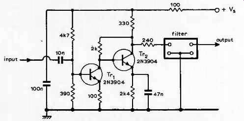
Fig. 3. Feedback amplifier consisting of voltage-to-current converter followed by a current-to-voltage converter has 26dB gain, defined by 100-ohm and 2k-ohm resistors. Output impedance of 90 ohms is made up to 330 ohms to correctly feed the filter.
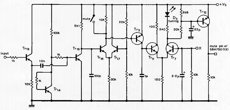
Fig. 4. Mute circuit, operated by the amount of amplitude modulation in the if. output, has the advantage of suppressing unwanted outputs due to detection on the non-linear regions of the S-shaped demodulation curve. Point X,fed from the demodulator via Fig. 5, feeds the tuning indicator, which is held off by 7V[ i in the presence of noise. An output from this circuit un-mutes the stereo output from SBA750 i.e. First five transistors are contained in SL3045 i.c.
Objective 1(a), is met by using a varicap-tuned front end. The performance of commercially-available units, although capable of improvement, is equal to our design objectives and presents the simplest solution. The unit chosen was the Mullard LP1186, which can be conveniently mounted on a printed circuit board. To achieve objective 2(a) more gain is required than that given by the above items.
This extra gain is provided by a two-stage feedback amplifier as shown in Fig. 3. The first stage acts as a transconductance amplifier, its gain being defined by the 100-ohm emitter resistor. The second stage then functions as a trans-resistance amplifier or current-to-voltage converter. The combination therefore has a gain defined by the 100-Q resistor and the 2-kOhm feedback resistor, and has a value of 26dB. The output impedance of this stage is around 90 ohms, and so a buffer resistance of 240 ohms is used to present the filter with its required source impedance of 330 ohms. This introduces a slight loss of gain, but ensures that the correct filter characteristic is obtained.
Muting circuit
The system so far described provides an audio output from an aerial input and could therefore be used as a tuner as it stands.
However, this is really where our story begins. If the above system is used, the first thing soon realized is that the interstation noise is highly objectionable. In fact it corresponds to a fully modulated signal over the entire audio band, since the input stage noise is sufficient to achieve limiting in the last IF stage, with a bandwidth equal to the i.f. filter pass-band.
In addition to this ear shattering blast, as a station is tuned a highly distorted version of the station program is received before the correct tuning point is reached, also at a high volume. This is of coarse due to detection via the "S" curve of the detector, and will be produced, at equal intervals either side of the correct tuning point. The net result of all this is design objective I (b), the suppression of all unwanted outputs. Put the other way round, the only sounds heard should be correctly tuned stations.
Audio muting is achieved by using the remote gain control facility of the SBA750. This is a pin connection usually taken to a remote potentiometer carrying DC only.
For our use the potentiometer is replaced by a p-n-p transistor (Tr12, Fig. 4) which is controlled from a number of sources.
Because the noise level is sufficient to produce a fully limited signal from the IF amplifier, the magnitude of this cannot be used to detect the presence of the station to un-mute the system, and this presents a problem. The solution is simple in concept.
What is required is a measure of the degree of limiting taking place within the IF amplifier, and this is easily monitored by detecting the amount of amplitude modulation present in the IF output. This has the advantage of detecting the spurious responses mentioned earlier, as these are in fact caused by the high-slope edges of the IF filter response converting the frequency modulation into amplitude modulation which is then detected by the quadrature detector.
The first device in Fig. 4 acts as a buffer to the IF amplifier output, which is very sensitive to capacitance loading. The next two devices form the amplitude detector. Transistor Tr14 is diode-connected and fed with a small current from the supply. As the five devices Tr13 to Tr17 are contained on one chip of silicon (SL3045), they have well matched base-emitter voltages, and this causes Tr15 to conduct the same current as Tr14. The 1-kOhm resistors in Tr14 and Tr15 bases provide a higher input impedance for the signal while preserving the voltage match, since the base currents are also equal.
The collector of Tr15 would sit at a relatively high voltage due to its smaller load resistance, but application of the IF signal (noise or "clean" 10.7 MHz), which is about 400mV pk-pk, causes this stage to rectify bringing its collector down to a low voltage.
The collector time constant is chosen so that the 10.7-MHz signal is filtered out but allowing amplitude modulation up to about 100kHz to be followed. This modulation can only be negative, as the IF is amplitude limited, and this produces positive-going signals, when present, at Tr15 collector.
The following transistor pair is biased with Tr17, normally on, so that this positive-going signal turns on Tr16 and hence Tr3, both of which are normally non-conducting.
In the presence of noise therefore the capacitor in Tr3 collector is charged rapidly taking the base of TV,, positive. This will happen in the presence of any form of a.m. noise or spurious signals, and may be used to mute the receiver.
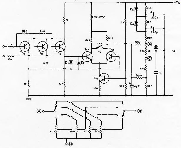
Fig. 5. AFC amplifier has its voltage swing limited to restrict AFC action to less than station spacing. Using a computer program, the tuning potentiometer network was optimized to provide uniform lock-in range over the tuned band and correct temperature compensation of the front-end. Diodes in potentiometer smoothing circuit allow quick charging of capacitors and keep settling time after switch-on short.
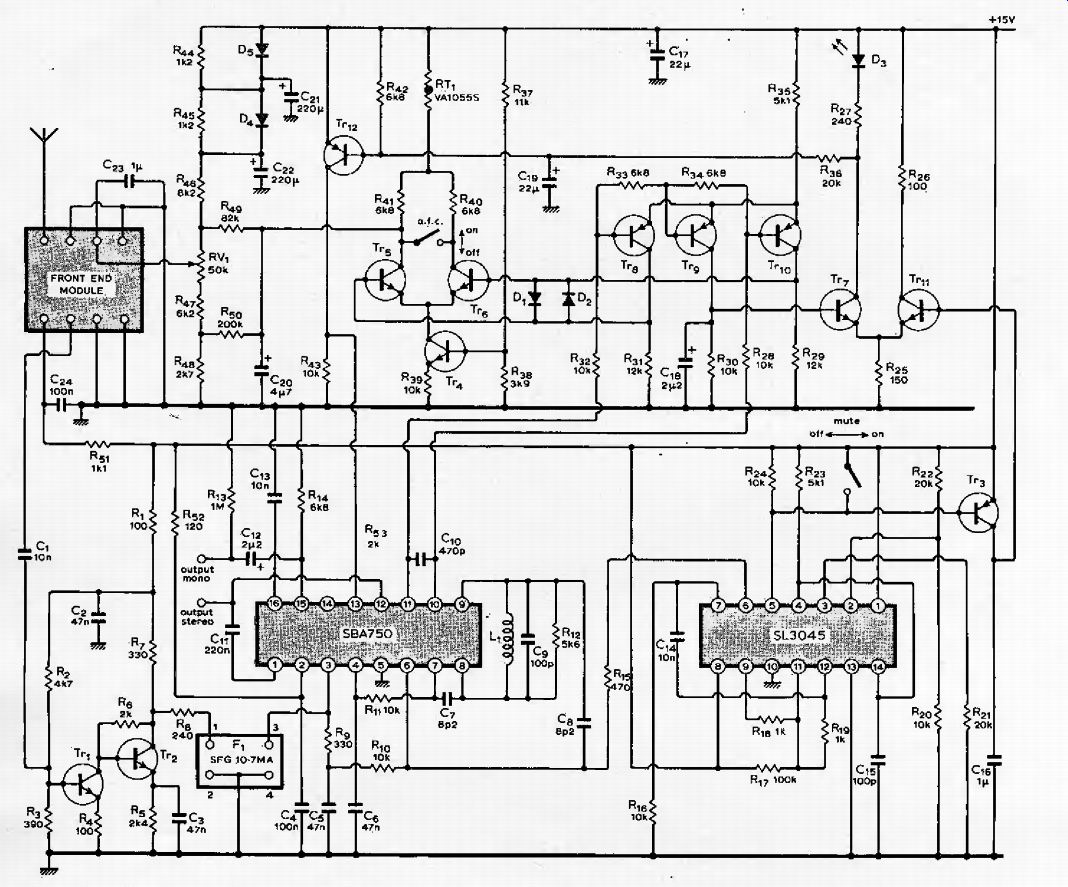
Fig. 6. Circuit of FM receive section of tuner with AFC muting and tuning indicator circuits. Frequency is displayed on a moving-coil meter (circuit in part 2). Resistors in this circuit should he 2% tolerance.
Single-lamp tuning indicator
There are many ways of meeting objective 1 (d). However there is a need to provide an indication which is readily understood by all, without the need for instruction, which ruled out several of the recently-used types.
These include the centre-zero meter and the two-lamp system, as neither of these provide a maximum response at the correct tuning point, which is the conventional mode of adjustment. This topic is to be covered in another article and the final design is shown in Fig. 5.
Inputs are taken from the balanced demodulator output via 10k resistors and fed to a long-tailed pair with the addition of a third transistor. This device is connected so that it conducts a maximum current (one third of the tail current) when the inputs are balanced. The collector of this (point X) is connected to the base of Tr7 (Fig. 4), the DC conditions being arranged so that at balance, and assuming Tr11 is off, Tr7 conducts 20mA into the single LED indicator, D3. This then has a maximum brilliance at the correct tuning point.
The Tr11 tuning indicator is extinguished in the presence of noise, since TV,, conducts away the current supply to it when its base is made positive by the action described earlier.
Objective 1(b) can now be easily obtained.
We only require the audio signal to be un-muted when there is a correctly tuned station being received, that is, when the tuning indicator is fully lit. The voltage-current characteristics of a LED are similar to those of a zener diode; therefore a 240ohm resistor is placed in series to give a voltage-varying point, and this is used to operate the mute transistor Tr12 (Fig. 4). The system will only pass a correctly tuned signal of significant signal-to-noise ratio.
Very weak stations, stations suffering from gross interference or aircraft flutter, spurious responses, and even strong stations which are mis-tuned by more than a few tens of kHz will be completely muted.
AFC circuit
There now only remains the objective 1(c), the provision of AFC This function received a lot of thought and discussion before the system described was finalized. A high degree of loop gain was required to reduce the tuning error to negligible proportions, but when this was tried, however, several disadvantages came to light.
Firstly it was found impossible to tune the receiver with AFC applied. One station would be captured and the tuning control rotated past several others on the dial before the original station was lost, and then it was not known which station had been recaptured. The tuning was completely ambiguous, in opposition to the main requirements and objective 1(d) in particular.
There are several expensive commercial tuners having this fault.
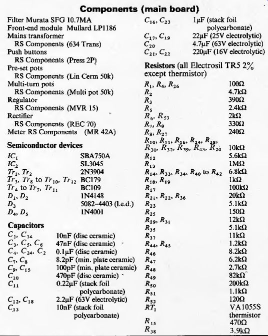
--- Components (main board)
-- Performance
The solution to this problem is simple in hindsight. What is needed is indeed high gain, but the frequency range should be restricted to less than the typical station spacing. This is easily achieved by limiting the swing voltage available from the AFC amplifier. One requirement for the above system to be successful is that the tuner should not have a temperature drift greater than the hold-in range of the AFC. This would anyway render the tuning calibration unreliable. In this design the AFC amplifier is used to provide temperature compensation independently of the hold-in range.
The circuitry used is shown in Fig. 5. The differential output from the tuning indicator triple is further amplified by Tr5 and Tr6. Due to the action of the triple there is a common-mode signal present in its output, and this is rejected by Tr5 and Tr6 by providing them with a constant-current tail from Tr4. Also under extreme mistuning it would be possible for Tr5 or Tr6 to bottom, causing a spurious output voltage and incorrect AFC action. Diodes D1 and D2 are included to prevent this from happening. They limit the swing available by clamping Tr8 and Tr10 collectors together at a maximum of 0.6 volts difference.
The AFC can easily be cancelled by closing switch S2, thus removing differential gain. The output voltage is now determined by the current from Tr4, which is fixed, and the total load resistance in the common mode. This includes the thermistor common to both collectors which is selected to provide the correct compensation of the front end, via the following network.
This network was optimized by a computer program to provide a shift of the end voltages of the tuning potentiometer by amounts representing equal frequency shifts. This results in a uniform lock-in range over the tuned band, and also correct temperature compensation. A possible method of switching and tuning potentiometers is shown; alternatively these may be connected in parallel provided that the total resistance remains at 50k.
The positive end of the tuning potentiometer, point A, is connected via a total of 10.6k to the positive supply, and any residual mains ripple at this point will modulate the tuning and produce a hum at the output.
Less than 0.1mV ripple is required to produce a hum level at least 60dB down on full signal. Therefore, the resistance is split and two 220uF capacitors inserted as shown. This has the desired effect, but produces a slow sweep across the tuning range as these capacitors charge up after switch-on. This is annoying as several stations are captured by the AFC in passing, before the wanted station is reached.
To overcome this defect, it is arranged that D4 and D5 diodes rapidly charge the capacitors, bypassing the 1.2-k resistors.
When fully charged, the voltage drop across these is insufficient to keep the diodes forward biased and they cease to conduct, allowing the full time constant to become effective. By this means the switch-on settling time is greatly reduced. These diodes can be seen in Fig. 6 which shows the discrete components and their inter-connection with the integrated circuit and frontend module.
The tuner circuit described provides the optimum performance with regard to the needs of all users. Operation is simplicity itself. The set is silent while tuning between stations and the tuning indicator is un-lit. When a station is encountered the tuning indicator lights fully and the set un-mutes. The tuning control is now left untouched in the knowledge that no further adjustment is required. If an adjacent station exists, the control may be turned further and the tuning lamp will blink off then on again and the new station will be heard; again no further adjustment will be required. This action is similar to turning a rotary switch. If this new station is further away, the set will remain silent until it is reached; mis-tuned stations cannot be received. If the AFC is disabled, for instance when hunting up-band for foreign stations, the tuning indicator allows a sensitive fine adjustment to be made. The mute facility may also be removed under these conditions to allow weak stations of less than 5 to 10uV to be received.
The design has been sufficiently thorough to ensure that the performance can be guaranteed, provided that the components specified are used and the layout of the p.c. board is as recommended. Setting up can be done with nothing more than a trimming tool, for the single tuned circuit, and a pair of eyes.
2 -- Stereo decoder, assembly and setting up
by J. A. Skingley and N. C. Thompson Plessey Company Ltd, Swindon
-------------
Fig. 7 shows the internal circuit of the SBA750. Pins 3 and 4 receive the input from the IF which is passed along the chain of five limiting amplifiers to pins 6 and 7. From here the signal is passed internally direct to the quadrature detector, and also externally via the quadrature coil and pins 8 and 9.
The demodulated signal is then available at pins 10 and 11, and it is from here that the drive for the AFC and tuning indicator is taken. This audio signal is taken internally to an amplifier giving a single-ended output on pin 12.
The stereo signal is taken from this pin and fed to the stereo decode board. It is also coupled via Cl! to pin 1, and after further amplification is available de-emphasized as a mono signal on pin 15. De-emphasis is accomplished by C13 on pin 16. Both Stereo and high-level mono outputs are therefore available.
The amplifier output to pin 12 can be attenuated by varying the current fed into pin 13. In this design pin 13 is open circuited to fully mute the amplifier while preserving the AFC drive from pins 10 and 11. This ensures that the receiver captures a station from the muted condition.
Improved stereo decoder
The stereo decoder is shown in Fig. 8. When this decoder integrated circuit was first used "birdy” type interference was experienced under certain conditions. The causes of this have been reported elsewhere, but it is worthy of further explanation judging by the lack of effort to remove it in expensive receivers.
The nature of a frequency modulated signal is such that a bandwidth many times that of the deviation is needed for accurate transmission and reception, around 300kHz often being used. The spacing of broadcast programs is however only 100kHz and this inevitably results in frequencies, front one station arriving at the detector of a tuner receiving an adjacent station. The products from the detection are however normally supersonic and therefore inaudible.
This is fine until we introduce stereo reception which involves demodulation of the stereo channel at 38kHz usually using square-wave switching. This process also demodulates signals around the odd harmonics of 38kHz, i.e. 114, 190, 266kHz etc.
The first two of these will produce audible signals from the adjacent channels at 100 and 200kHz away from the wanted station, giving interference centered on 14 and 10kHz respectively. These sound like high-pitched twittering sounds commonly called birdies.
Knowing the cause, the effect can be greatly reduced, if not completely eliminated. The wanted stereo information extends up to 53kHz, so by filtering the signal above this frequency before the stereo decoder, the unwanted adjacent channel signals can be attenuated. This also brings about an improvement in signal-to-noise ratio during stereo reception, as noise above 53kHz is also reduced. Such noise can be demodulated down to the audio band by the harmonics of the 38kHz switching frequency in a similar fashion to the adjacent channel signals if it is not removed.
The filtering required is carried out by Tr1 in Fig. 8, which also shows the complete stereo decoder. (This circuit has been built on a separate board, and for this reason the components have been numbered independently). Transistor Z>3 forms an active filter of the Sailen and Key type and provides a second-order response. There is an additional pole supplied by C10 between pins 10 and 11 of the SBA750 and this, together with the two poles of the active filter, combine to give a three-pole optimally flat response up to 53kHz, followed by a sharp roll off of 18dB per octave. This transistor is directly coupled and biased from pin 12 of the SBA750, and its output fed to the input of the decoder integrated circuit.
This decoder is of the phase-locked loop type, and in appreciating the advantages of this form of decoder, it is worth looking briefly at the conventional type. These decoders work by generating the necessary 38kHz switching frequency either by converting up the 19 kHz pilot tone, or by phase locking a local oscillator to this pilot tone.
The 38kHz signal may then be used to switch the multiplex signal into its two separate paths. Obviously, this switching must not only be at the correct frequency but it must also be in synchronism with the original coding. In other words the phase of the coding and decoding signals must be identical. If a tuned circuit is used as in the conventional decoder to separate the 19kHz from the audio, then a high-Q tuned circuit must be used to avoid phase jitter from the residual audio. A high-Q tuned circuit however has a high phase shift for a small amount of mis-tuning. For this reason a low Q would be required. Hence there is a compromise.
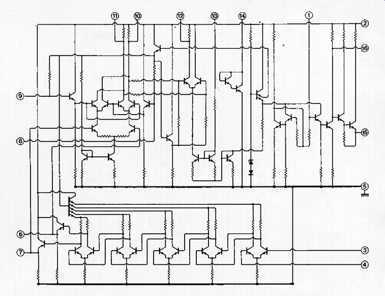
Fig. 7. Internal circuit of SBA750A i.e. includes circuitry if. amplifier
(below) balanced quadrature detector and a.f preamplifier (used on mono only).
Signal to un-mute output is applied from Fig. 4 to pin 13. Drive for AFC and
indicator circuit is taken from pins 10 and 11 via circuit of Fig. 5 and drive
for mute circuit is taken from pin 6.
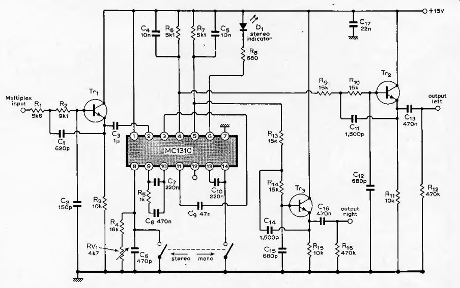
Fig. 8. Decoder circuit includes an active filter to roll-off response at
18dB per octave above 53kHz to prevent "birdies" that result from
interference between odd harmonics of 38kHz and adjacent carriers. Two further
active filters remove the 38-kHz harmonics from the outputs.
The phase-locked decoder operates by generating a 38kHz signal (in this case a 76kHz signal divided by two). This is divided by two to give 19kHz which is compared in phase with the pilot tone. The difference between the two is used to provide feedback, and hence phase lock the local oscillator to the pilot tone. The time constant of the feedback path may be made long so as to reduce the phase jitter to a negligible amount. This is equivalent to producing a high-Q tuned circuit, but one which cannot drift in phase provided the loop gain of the feedback path is high. This system also has the advantage that no coils are required.
The complexity required dictates the use of integrated circuits on economic grounds, which has the added advantage that fewer corners need be cut in the design stage, so that the full potential of the system may be realized.
Two more active filters have been added, one per channel, formed by Tr2 and 4 Tr3 (Fig. 8) and these are directly biased from the integrated circuit. Their function is to remove unwanted signals from the outputs, such as the 38kHz sub-carrier and its harmonics, which could otherwise cause trouble when tape recording.
The MCI 310 has a direct output for a stereo indicator lamp and the facility for disabling the decoding process if desired. In the tuner described this is implemented by a second pole to the switch which also stops the oscillator to prevent any possible interference. The stereo decoding may need to be stopped if the signal is weak and a poor signal-to-noise ratio is obtained. Reverting to mono reception will provide an improvement. You may prefer to use the mono output provided from the receiver board, but this will need attenuation to give a compatible level when switching to mono. The tuner will, of course, automatically give a mono output in the absence of a pilot signal.
Construction
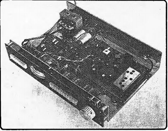
Layout and general presentation of the tuner is largely a matter of personal choice, and in this connection the mechanics described represent only our solution, offered as a suggestion. The layout of the printed boards are critical, and it is strongly advised that the board design offered here is used. The system employs a generous amount of gain at high frequencies and even small deviations from the layout given could prove troublesome. This layout, given in Figs 9 and 10, follows good engineering practice and ensures stable performance.
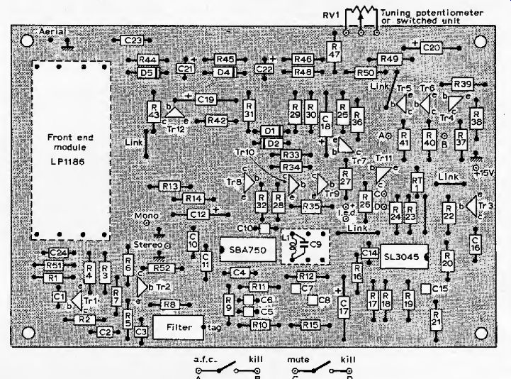
Fig. 9. Component layout for Fig. 6 is critical and p.c. board shown in Fig.
10 should be used.
Points A and B connect to the AFC switch and points C and D to the mute switch.
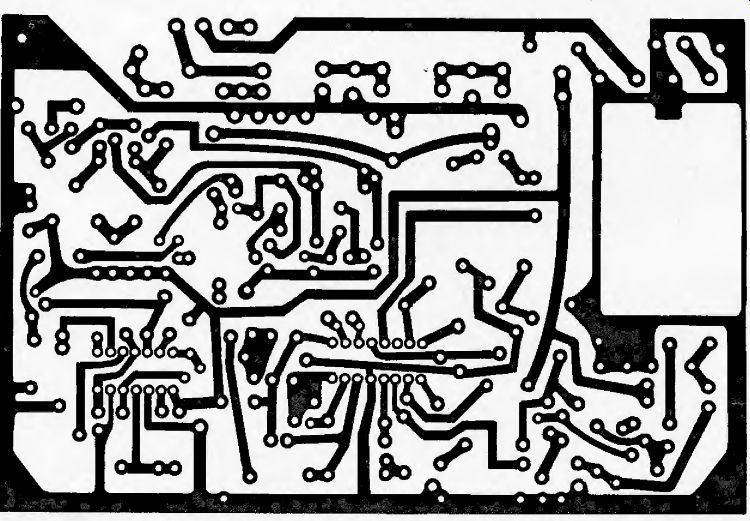
Fig. 10. Copper side of printed board, actual size. Component side shown above.
When assembling a board of this complexity it is a good idea to insert a few components at a time, solder these and clip their leads before inserting a few more. Start with the passive components and finally the transistors, integrated circuits, filter and front end. There are four wire links and these are made using discarded resistor ends.
The single coil is 15 turns of 3.3 s.w.g. cotton cord wire, close-wound on a Neosid type A screened assembly using an F16 screw core.
Before soldering the wire ends of this, insert the capacitor C9 (100pF) into the same pins as the coil. This capacitor is slim and is easily accommodated within the can.
The emitters of the transistors are adjacent to the tag on the can. Transistors Tr1 and 7>2 are an exception to this. Insert so that the flat face of the plastic package is on the opposite side to the base of the triangle.
If the center (case) lead is bent forward towards the flat all these leads will fall into place.
Finally, solder twisted-pair wires at points A and B for the a.f.c. switch and C and D for the mute switch, together with pairs for the tuning indicator lamp (observe polarity), audio outputs and 15-volt power supplies.
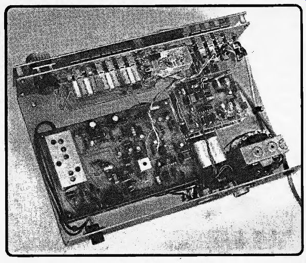
Mount the two boards on fin brass pillars at the four corners, preferably on a metal chassis to ensure good earthing and screening.
The chassis system (Fig, 12) was constructed from 16 s.w.g. aluminum sheet, a piece II in square being required. After drilling the chassis is bent into a U-shape where shown, and the front panel fitted on 0.5 inch brass pillars. This can be made of aluminum, sprayed and marked with Letraset. Alternatively, perspex may be used, marked in mirror image and sprayed on the reverse side. There are many ways open to home constructors these days, and the production of a. professional finish is largely a matter of ingenuity and personal taste.
The front panel is made 0.25-in deeper than the front edge of the chassis to allow the use of rubber feet on the chassis, yet leaving a smaller clearance beneath the front panel. A false front panel has the advantage of hiding most of the screws and allowing the push buttons and meter to protrude the correct distance. It also allows space for a hidden pilot lamp to illuminate the meter. A cover made of polished wood or sprayed metal may easily be made to fit over this chassis, consisting of inverted U-shape forming the sides and top. This should be about 8 or 8 1/2 in from front to back, depending on the front and back overhang desired, and the sides the same drop as the front panel.
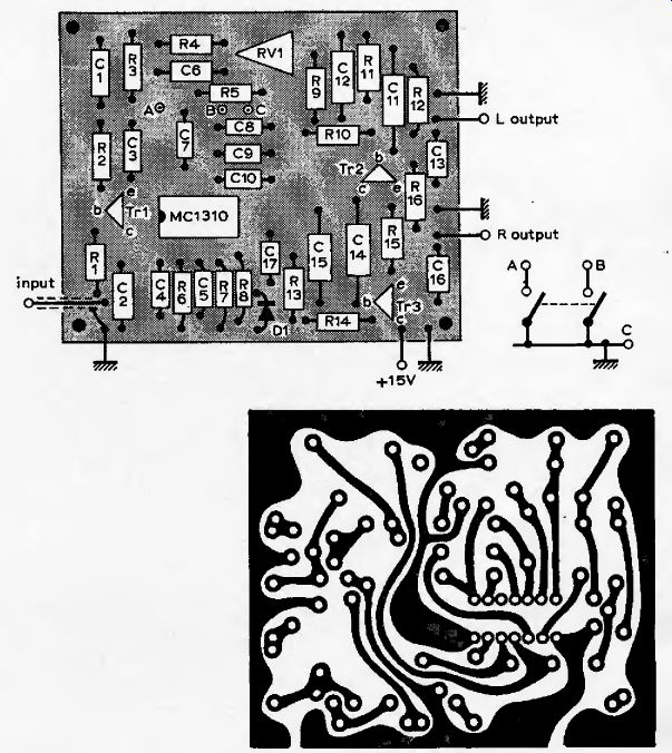
Fig. 11 Stereo decoder layout. Points A, B and C connect to mono/stereo switch
shown actual size.
--------
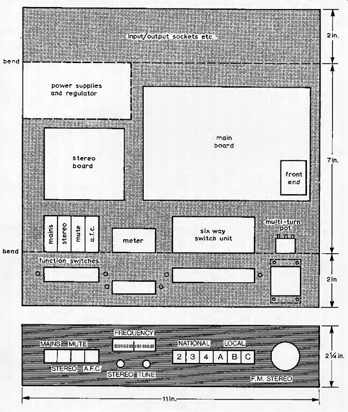
----- Chassis for complete receiver can be made from an 11-in square 16-s.w.g. sheet of aluminum, bent into a U-shape (Fig. 12, above). Separate front panel and cover improve appearance. Drive circuit for frequency meter gives linear frequency scale, varicap non-linearity being matched by matched-pair integrated circuit (Fig. 13, below). Layout on right shows preset potentiometers and frequency meter components (Fig. 14).
The only difficulty is in mounting the ten-turn potentiometer which has a short spindle and must be brought forward 1/2 in from the chassis. This is achieved by cutting a clearance hole in the chassis 1-in square and mounting the potentiometer on a strip 1 x 2-in held on ¼-in pillars, or long screws and double nuts. The spindle will then protrude from the front panel by the correct distance.
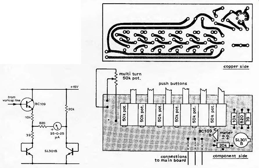
The prototype used six push buttons for pre-selected stations mounted on a printed board with the pre-set potentiometers between them. This resulted in a compact switch unit, but the method necessitated a minor trimming of the width of the potentiometer by rubbing their faces with emery paper until a sliding fit was obtained. This board also held a drive circuit for the meter used to display the frequency. This is shown in Fig. 13,and the PCB in Fig. 14.This unit may be mounted on 0.1-in pitch Letrokit board and hand wired if preferred, using the PCB layout as a guide.
The meter drive circuit is basically an emitter follower driven from the tuning voltage, but the addition of a Plessey SL301 matched pair as shown results in a temperature-stable law-bending circuit producing a linear frequency scale from the non-linear law of the front-end varicaps. The meter is and RS Components miniature edge meter MR42A, 25-0-25 uA. By removing the two screws the case may be removed and the scale lifted from its mounts. A wipe with acetone or nail varnish remover removes the lettering which may then be replaced with a suitable frequency scale using Letraset-or free-hand if you have a steady one! Take care to avoid damage to the pointer, and the case should be replaced to exclude dust while the scale is being redrawn. Final calibration is done, by mechanical adjustment of the zero adjuster while receiving a known station.
It is important that the power supply should be free of ripple and temperature stable, and this is achieved by a regulator integrated circuit RS Components MVR15V. This, together with bridge rectifier REC70, 1000 uF capacitor, and transformer (634) from the same supplier complete a stable power supply for little effort.
Top-grade components were used to ensure reliability and consistency of performance. It is strongly recommended that the components specified are used. There are parts of the circuit which require 2% resistors, for example, to ensure correct biasing and balance of the tuning point and a.f.c. circuitry.
------- Components for suitable power circuit, above, were listed in part 1.
Setting up and testing
When the boards have been wired and mounted make the appropriate interconnections. Connect LEDs and switches, and check everything before switching on. Put switches in the AFC-off and mute disabled positions, and leave the aerial unconnected.
Do not adjust the front-end module which is pre-aligned and should not be touched.
Under these conditions there will be a band of noise defined by the IF filter passing through the limiting amplifier to the detector. If the core of the single coil is adjusted until the tuning lamp responds and be trimmed for maximum brilliance, the detector will be correctly adjusted to the center of the IF pass band.
Now connect an audio amplifier and speaker. A loud smooth hiss should be heard. If the mute switch is operated this hiss should be silenced and the tuning lamp extinguished. Connect the aerial--a short length of wire--may receive several stations and, with all push-buttons out, adjust the ten-turn potentiometer to find stations.
Observe AFC action by mis-tuning a station until the tuning indicators is just extinguished and the output muted. Switching in the AFC should recover the station.
A good aerial will now reveal anything around a dozen stations. The three least noisy should prove to be the national stations, and the frequencies of these are given in the local Radio Times. Trim the meter using the internal adjuster and obtain pre-set stations by pressing the appropriate button and adjusting the adjacent pre-set potentiometer. If this adjustment procedure cannot be achieved switch off and check all components and interconnections. Particularly check for incorrect polarity LEDs and capacitors, misplaced n-p-n an p-n-p transistors, capacitors omitted in coil assembly or wrong number of turns.
If the alignment of the main board is achieved set the stereo decoder. This involves adjusting the oscillator using the single pre-set potentiometer. First find a transmission known to be stereo; check with the Radio Times. Ensure that decoding is not disabled by the switch provided and adjust until the stereo indicator lights. Now release and pre-press the stereo switch and adjust the potentiometer until the LED lights in the shortest possible time after the switch is pressed. This is the correct setting.
Finally, a word about aerials. This tuner will receive stations on a few feet of wire, but if the full potential and maximum signal-to-noise ratio is to be obtained, a good aerial is essential. Any system can only be as good as its signal source, be it a. pick-up cartridge, tape head or radio aerial, and this can easily be the weakest link in the chain.
Modification. A resistor of 2k should be added in place of the wire link shown just below R43 in Fig. 9. Because Motorola have altered the specification for the MC1310, a 150-ohm resistor should be added in the supply line to the decoder board, returning the LED current directly to the +15V rail. Increase C17 to 20uF to decouple this.
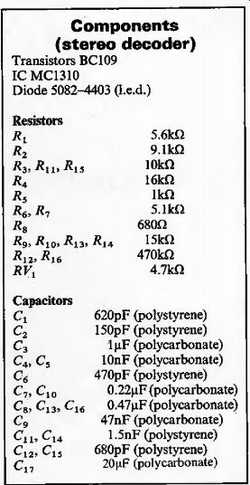
--------- Components (stereo decoder)