An update of two 1972 WW articles
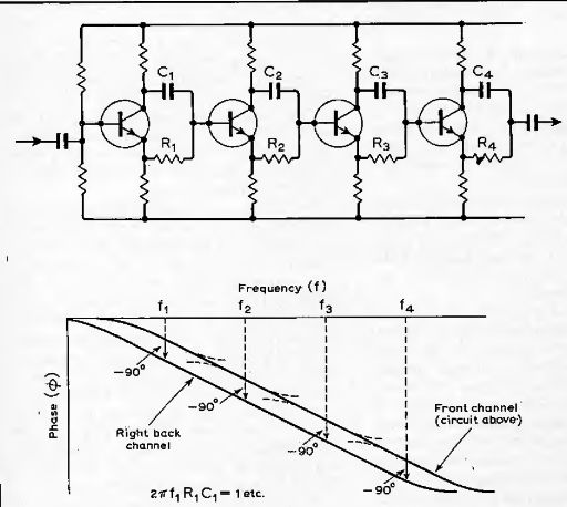
Fig. 1. A 90° phase difference over a wide band between two channels can
be realised using two sets of cascaded phase shift circuits of the kind shown.
The difference in phase between the two cascaded circuits is made 90°. In
practice the phase-difference/ frequency response is rippled but the amount
of phase ripple can be kept within prescribed limits.
Quadraphonic systems, here interpreted as attempting to convey sound direction with four loudspeakers using either two, three or four transmission channels, use matrix circuits to suitably organize the information into the required number of channels.
The approach in the January and February 1972 WW articles applies to the practice in recording studios of preparing four-track mix-downs for quadraphonic use. It does not represent the only way of achieving surround sound within a finite number of channels; but the alternate microphone mixing techniques are a comparative rarity. The justification for using such tapes is a commercial one; record companies, having built up stocks of multitrack tapes over the years, will obviously want to remix them into a four-track format and use them with quadraphonic playback in mind.
What this multi-track approach will never do of course, is to capture the "ambience" or reverberant qualities of the live acoustic scene. This ideally requires a microphone technique that will take sounds from all directions in such a way they can be played back with the apparent reproduced directions corresponding with the original directions.
This is the aim behind the "ambisonic" proposal of Peter Fellgett for instance, whose concepts of course, do have relevance to the multi-microphone, pair-wise mixed master tapes. As Fellgett has argued1 , any worthwhile technique that can adequately cope with sounds from any direction should be able to handle these signal sources as well.
Matrixing, in connection with quadraphonic systems, is one way of combining separate ("discrete") audio channels into a lesser number so that channels are kept sufficiently separate to be retrievable by a suitable "dematrixing" process, albeit with large amounts of crosstalk from other channels.
Matrix circuits are frequently used in situations where information taken from separate signals is required to be re-arranged for some reason (typically to make signal processing easier) without loss of information.
In stereo, for example, left and right-channel signals can be used to form sum and difference signals that are equivalent in that no loss of information has occurred.
Circuits that achieve such re-organization are called 2-2 matrix circuits. Another example of a similar matrix circuit occurs in colour television, where color subcarriers provide two difference signals, RY and B Y, which are fed to a resistive matrix to provide GY. This is possible because Y = 0.3 R + 0.59G + 0.11B, (The three color difference signals are then fed directly to the c.r.t. grids, with a --Y signal at the cathode.
Alternatively, +Y is added to the three color difference signals to provide R, G, B.) In the mathematical sense a matrix is merely an array of rows and columns of numbers, but it is more in an electrical sense that it is applied in this context. One can think of an electrical matrix as an array of intersections between input and output lines, between some of which may be connected linear or non-linear elements. The result of this arrangement is a coding of the input onto the outputs. A binary-to-decimal coder or decoder is a good example of such an electrical matrix.
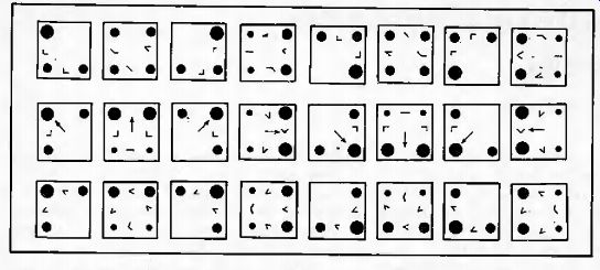
Fig. 2. Speaker outputs for the commercial two-channel matrix systems for
eight intended source directions (see arrow in middle). Blob size indicates
speaker output and angles represent phase between speakers. Top is the basic
SQ matrix, middle is the QS matrix and bottom is the BMX matrix.
There are also differences in mono and stereo compatibility of the three systems, see Table.
In a simple amplitude matrix the gains between inputs and outputs can be set; in a phase matrix it would be a phase difference between a pair of lines that can be set.
Considering first an amplitude matrix, one can visualize a general linear resistive network where four input signals, say A, B, C, D, are fed into two outputs, say L and R, with A contributing an amount a to L and an amount a' to R, and similarly for B, C and D (like that of Fig. 2 in ref. 2). In retrieving the original inputs from the two channels L and R, outputs are derived by mixing different amounts of L and R, a special case being when one takes an amount u of L and a' of R to form one of the four outputs. Thus …
aA bB -f cC + dD = L
a'A + b'B + c'C I d D = R
Substituting the equations for L and R in the above gives (for the first output only)
A' = ah + a'R
B = W. + b'R
C - ch -1 c'R
D' dh th d'R.
The first thing one notices is that for an input to this network, or matrix, of A only, the output A' has components from the B, C, and D inputs, i.e. crosstalk. Matrixing works because one can make (a ' ja' 2 ) > ah A ivW. for example. It can be shown that if the D contribution is made zero by suitable choice of coefficients, the other contributions cannot be smaller than -3dB. The trouble with this simple sort of amplitude matrix is the anti-phase component that is always present in four-speaker playback which upsets the apple cart as far as accurate portrayal of direction is concerned (ref. 2). The way round the problem is to use QO- ' phase difference circuits (two circuits of the kind shown in Fig, 1 can be used) and the three current quadraphonic matrix systems use such circuits to distribute the 180 deg phase difference in one of three ways (see next section).
Commercial systems
For adequate representation of sound field direction it can be shown that for frequencies where head dimensions are small in relation to sound wavelength, three transmission channels will do; but it is possible to do it with two provided a directional ambiguity is resolved by suitably organizing a 180° phase difference. There have been in-between proposals, like that of R. Berkovitz in which it is proposed to transmit ambiguity resolving information in the form of a "key" signal, sent with one of the two channels at a high or inaudible frequency.
But current commercial two-channel systems (SQ, QS, BMX) all effectively divide the 180° of phase difference in different ways, the newcomer to the market place being BMX which distributes the phase in such a way as to be least bothersome.
Specifications and main characteristics of the three commercially-produced two-channel matrix systems are compared in the Table and in Fig, 2 which indicates speaker amplitudes and phase difference for sounds intended for eight different directions. It shows clearly the large amounts of crosstalk in all the systems-a fact of life in two-channel systems-the differences between them being one of organizing the crosstalk component amplitudes and phases to best effect. Taking the basic systems without any embellishment, it would seem that the SO matrix does the poorest job, while the BMX matrix provides the most clues as to source direction.
The SQ encoding system concentrates on minimizing front left-right crosstalk at the expense of mono compatibility and directional anomalies in quadraphonic playback. Image positions around two opposite corners are compressed and center front-to-back crosstalk is severe (though much Improved with the "10%-40%" blend decoder, see Table on P. 86). The QS/RM system gives speaker amplitudes as shown for BMX in Fig. 2, but with phases that do not seem to be as helpful as in BMX. Mono compatibility of QS records is poor (see Table) and in stereo there is a crosstalk of 7.7dB, narrowing the stereo spread, and which is accompanied by back sounds appearing to come from beyond the two speakers. (Mono compatibility is improved for broadcasting by phase shifting one channel with respect to the other by 90°.) BMX achieves its performance-about the best that can be expected from a 4-2-4 system in the quadraphonic and mono modes--at the expense of a W phase difference between channels in stereo.
Variomatrix. Methods of circumventing the various defects rely either on using variable gain or blend circuits to suppress crosstalk components in the four-speaker mode or in adding further audio channels. Circuits and operation of variable gain or blend for the SQ system have been published in Wireless World before, but at the time of going to press details of the latest developments in SQ decoders were still not available.
The Sansui Variomatrix technique is based on a phenomenon of "directional masking" in which it is argued that the direction of a sound is less easy to perceive in the presence of a more dominant sound, following within 10ms, Sansui say that effects equivalent to those of a "discrete" system are obtainable from a matrix system that reproduces the dominant sound with utmost directionality and the lesser sounds with less precise directionality (within a time span of 10ms), carefully and openly adding the rider, "provided such obscuring of directionality is within limits dictated by the psychoacoustics of four-channel listening which is yet to be studied seriously". So Sansui use circuits additional to the basic QS matrix to detect the direction of the dominant sound (in level) and derive suitable control signals to alter the matrix parameters and reduce crosstalk components for that direction (within maximum periods of 10ms). The reduction of crosstalk is done in a symmetrical way, both crosstalk components being altered equally, to avoid changes in image position. At the same time crosstalk components of weaker sounds are increased.
While there are similarities in the way control signals are derived with the gain control techniques applied to SQ decoders, the method is different in that weak sounds are not so severely mislocated.
------------
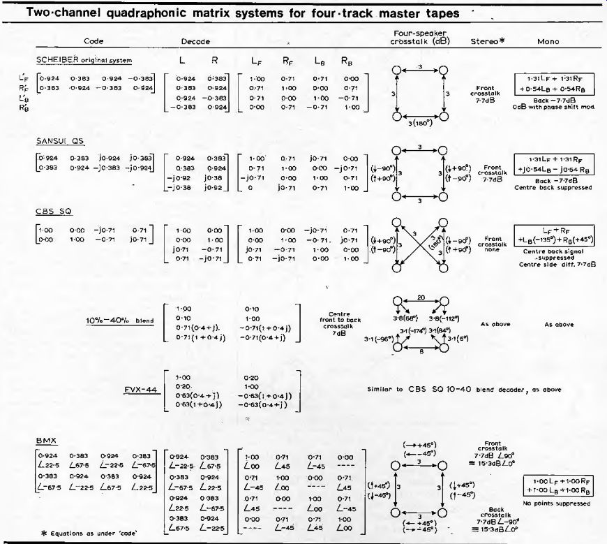
Table gives data for basic two channel quadraphonic systems.
Data for gain-control systems for SQ, variable blend system for QS, and the 4-d-4 QMX brother of BMX are not included.
Two-channel quadraphonic matrix systems for four-track master tapes
Phase detector circuits determine the intended location of a sound image. Front-to-back sound source is detected by comparing the phase of the two transmission channels, L and R, while left-to-right sound positions are determined by comparing the left-channel signal and the sum of the right signal, phase shifted by 45°, with that of the difference between these two signals.
The Variomatrix circuits can be applied to SQ encodings too, with the result that center front-to-back separation is improved from 0-db to at least 6dB. It can also produce four-speaker playback of stereo records.
Phase-encoded matrix
The other basic way of representing direction of a sound using two channels is by carrying an omnidirectional signal in one channel and another omnidirectional signal in the other channel but phase shifted by an amount that depends on the direction of the sound. The omnidirectional signal, which is the sum of all sound sources, while being by definition an ideal mono signal is not in itself in a convenient form for stereo transmission-neither is the phase-encoded signal-so they can be sum-and-difference matrixed, the new sum forming a left transmission signal and the difference forming the right signal. A mono pickup would then respond by producing the original omnidirectional signal.
Using the expression exp/0 to represent phase angle, to be made the same as the bearing angle, the left and right signals become I + exp(-yt?) and I -expf -/t?) in the case of sounds encoded to the optimal BMX matrix of Cooper and Shiga. (In these expressions, unity represents the omni or directionless signal.) In decoding, the two are sum-and-differenced matrixed, providing a mono or omni signal and a phase-encoded signal, the last-mentioned of which is phase shifted by an amount 0° say, a speaker bearing angle. This is then added to the omni signal to provide a speaker signal.
Fig. 3. Directivity patterns obtainable with BMX (top) and QMX (bottom) twoand four-channel systems. Speaker amplitudes are obtained from the intersection of the polar curve with the lines joining the four corners. In the new QMX carrier-channel disc, known as UD-4, the improved directivity of the four channel matrix is obtained after demodulating carrier channels.
For a speaker that is at the same angular location as the source the speaker output is a maximum, for an opposing speaker the output is zero; and for speakers at T90D from the source the outputs will be -3dB and phase shifted by ±45°. The maximum phase difference of 180° that occurs between speakers in the Scheiber system and which is reduced to 90 degree in the Sansui system, is now down to 45° (see Fig. 2). Signals for the four inputs from a four-channel master tape will appear as shown in the Table. The coefficients, which show similarities with the Scheiber and Sansui QS coefficients, can be seen to result from combining by addition and subtraction the omni signal, Lf + /Jf + is + Rb with the phase-encoded signal is exp -;
, 135' + RF exp-;450
i . . ,
The inventors of this particular form of phase-encoded matrix approached the design from a viewpoint of bearing-angle harmonic synthesis 3 , in which directional functions are accurately represented using a limited number of channels and optimised by a statistical technique. The workings of Cooper and Shiga show that as well as the BMX two-channel system there exists an hierarchy of systems, of three, four, five, etc. channels, each being optimum in conveying directionality for that given number of channels and with the virtue that channels can be added or taken away while leaving the system still optimum.
The third and fourth channels turn out to be phase-encoded omni signals, but with the opposite of, and double, the BMX phase angles respectively (effectively the first two, three or four terms of a bearing-angle Fourier series). This four-channel matrix system, called QMX, is the basis of the new discrete system, UD-4 (see next section). There are many other matrix systems that have been proposed or discussed, like that developed at the BBC Research Department, the three and four-channel systems listed by Eargle 4 , the telrahedral system first pointed out by Geraan, and the periphonic (including height) ones listed by Gerzon who conceived of an hierarchy of systems using "spin" and spherical harmonics.
None of these have been taken up commercially, except for the Cooper/Shiga hierarchy of horizontal-only systems now marketed by Nippon Columbia in the QMX format as UD-4, which could be considered to be a special case of the Gciv.on periphonic family. (Though horizontal in concept the system does lend itself to the addition of height information.) Discrete systems Assuming, as almost everyone does, that surround-sound in its quadraphonic form is here to slay, the question of how to get four separate channels of audio from a compatible disc record was bound to raise its head, whichever way those four channels arc used.
JVC with their CD-4 record system have gone a long way to achieving this end, but there still remain HF distortion problems and sensitivity to various inequalities.
Apart from possible mistracking of the complementary noise suppression circuits, there can be differences in phase and amplitude of the baseband and carrier signals, leading to crosstalk and consequent direct image displacements. For instance, with a carrier modulation level greater than baseband level, side images are shifted toward the speakers away from center and centre-side images become even more unstable than they already are. With a lesser carrier-channel level the side images shift the Other way and center front and back images become less stable.
There can also be h.f, baseband losses at the inner point of the groove spiral, h.f, losses due to fall off in pickup response and crosstalk distortion products due to tracking and tracing difficulties, causing phase modulation of the carrier. While "down-talk" may be negligible, "uptalk" is not because of errors inherent in tracing and tracking.
Such sources of crosstalk are minimized in the QMX carrier-channel system of Cooper, Shiga and Takagi. In the UD-4 disc record system that is based on QMX, the baseband channels are encoded to the BMX matrix, and speaker outputs for this are shown in Fig. 3 (top). When the BMX channels are combined linearly with the carrier-channel matrix, to give the overall QMX matrix, the speaker outputs will be as shown in Fig. 3 (bottom). The result of inequalities in level and phase between the baseband and carrier modulations is a broadening of the QMX patterns Fig. 3 (bottom) into the BMX patterns (lop). Th's broadening is gradual, continuous and symmetrical, there being no change in rotational or axial symmetry. The result is that there are no direct image shifts, merely an increase in the risk of mis-localization because of the broadening.
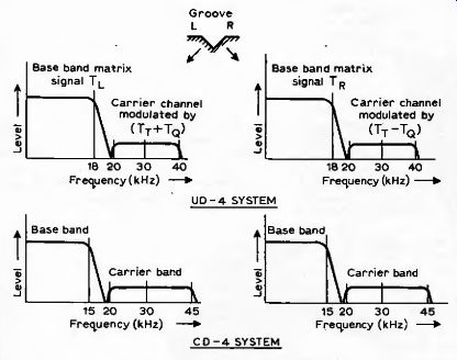
Fig. 4. In the UD-4 system the carrier channels can be narrow bandwidth
without affecting overall response, with a consequent gain in signal-to-noise
ratio.
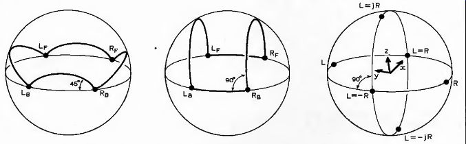
Fig. 5. M. Gerzon's energy sphere representation of coding sounds onto two
channels. The "pan locus" shown left applies to a pan-potted amplitude-coded
system with 45° phase differences between adjacent points-the locus for
the phase-encoded BMX system is similar but turned vertically through
90 degr. Middle diagram shows QS pan-locus, and diagram on right shows
points on the sphere corresponding to different phase and amplitude relations
between two channels.
Another important feature of the UD-4 QMX approach is that the carrier-channel bandwidth can be restricted, without affecting overall response, not possible with the CD-4 matrixing, with consequent benefits that accrue from limiting HF information in the carrier channels. Localization tests 6 on a selected group of young people in an anechoic chamber (with speakers hidden from view) and using spectrally-weighted intermittent noise with bandwidth limited to 130 Hz to 3 khz did not show significant degradation in accuracy.
The restriction in bandwidth after demodulation of the carrier channels means that the noise and distortion contribution is reduced. A gain in signal-to-noise ratio of around 10 to 12dB is obtained over a full-band system. In LJD-4, the gain is used to dispense with the noise reduction system, reducing complexity, cost and eliminating any errors from mistracking.
Actually, recorded bandwidth of the carrier channels is made 6kHz so that when the state-of-the-art allows, 4dB of signal-to-noise ratio could be sacrificed for the extra bandwidth by making the carrier channel bandwidth in playback equipment 6 instead of 3kHz, Maximum deviation of the 30kHz carrier is limited ± 10kHz, giving a lower top frequency than on CD-4 records (Fig. 4) with less dependence on the pickup cartridge.
Spherical representation:
The simple view adopted earlier in looking at matrix systems is not the only one, though it is helpful to some people to look at them this way. A more useful approach is the geometric model thought up by Michael Gerzon, who calls it the-energy sphere, and Peter Scheiber, who calls it the representative sphere. By conveying a sound source, S, say on two channels, L say, equal to Scosd/2 and the other, R say, equal to 5, sin 0/2, source direction can be portrayed, defined by (i/2 = tan 1 L/R.
Representing this angle on a horizontal circle is the starting point for introducing phase angle. This corresponds to tilting the circle about a diameter through an angle, say the circle ultimately describing a sphere.
Thus encoding direction as phase difference between two channels is equivalent to this tilt and if amplitude ratio between channels is unity the phase angle is measured around a vertical circle.
The various ways of coding a sound arid its direction onto two channels, i.e. by phase or amplitude coding, or any combination of both, can be defined by the locus of a point on the sphere that makes angles phi and theta at the center with the vertical and horizontal planes.
The "regular matrix" is one in which direction is conveyed by amplitude and is defined by a locus that is an horizontal great circle. The locus for the phase-encoded system described earlier is a vertical great circle.
To decode a sound direction, the two channels are added each with a phase and amplitude appropriate to each speaker position. It can be shown that, given a single input, this process leads to outputs the amplitudes of which follow a law governed by. a cardioid shape. This cardioid-type directional resolution means that an output from a two-channel system fed to a speaker for which the decoding point on the sphere corresponds to the encoding point will feed a speaker with maximum signal. A decoding point that is diametrically opposite will give zero output (infinite crosstalk), and for points at ±90° output will be 3 dB down on maximum.
Representing matrix systems on the sphere
The sphere model has geometric properties that relate to matrixing. The transformation on the sphere surface due to matrixing is a conformal one in which angles between curves on the sphere are preserved and in which circles change into other circles on the sphere. The simplest kind occurs with 2-2 matrixing which results in a rotation of the sphere.
The constraint to be met for this to happen is that the sum of the squares of amplitudes coefficients of the L and R channels must be a fixed multiple of the sum of the square for the new matrixed channels. This is clearly met in the case where the L and R signals are matrixed into L cos 0/2 + R sin 0/2 in the left channel and R cos 0/2 -L sin 0/2 in the right, the sphere being turned through 0 about the vertical axis. (Incidentally this also corresponds to rotation of the direction of stylus motion in a stereo groove by 0/2.) The preservation of angles between circles is helpful in visualizing pan-potting. In a 4-2-4 matrix system the four inputs are represented by four points on the encoding sphere. In pan-potting between a pair of these inputs, or points, the "pan locus" follows circular arcs on the sphere. If the two inputs, or points, have a phase difference the arc angle at one point is equal to the phase difference and joins the other point at the same angle.
If the phase difference is zero, the arc is the shortest great circle; if the difference is 180° the arc is the longest great circle.
The difficulty with early systems like Dynaco/Hafler, Electro-Voice, Scheiber, i.e. of the non-phasor, amplitude-encoded kind that of a 180° phase difference between rear channels-shows up as a doubling back of the pan locus, a kind of double horseshoe shape.
In many ways a great circle locus is best, like the amplitude-coded regular matrix "optimal" specification (an horizontal great circle), the phase-encoded "optimal" system of Cooper and Shiga (a vertical circle) and Gerzons SMQ idea (a great circle tilted at 45°). Any one of such great circle systems can be converted to another by a relative phase shift between channels.
But they require special microphone techniques and pan-pots that encode directly onto the two channels. For encoding four track mix-downs compromise raises its head and for two-channel systems, the 180° phase anomaly has to be dealt with.
One way is to distribute this in four lots of 45° suggested by various people around 1971.
Gerzon and Eargle thought of doing this to an amplitude matrix (Fig. 5 (left)) while Cooper and Shiga proposed it with a phase-encoded matrix (Fig. 5 (left) with the horizontal axis turned to the vertical), To end this brief look at the energy sphere, Fig, 5 also shows the way Sansui chose to distribute phase in their QS/R.M system (middle), and some important points on the sphere (right).
References:
1. Feilgett, P., "Directional Information in Reproduced Sound" Wireless World vol. 78 1972 pp. 413-7.
2. Shorter, G., "Four-Channel Stereo" Wireless World vol. 78 1972 pp. 2-5.
3. Cooper, D. H. and Shiga, T., "Discrete-Matrix Multichannel Stereo" J. Audio Eng. Soc. vol. 20 1972 pp. 346-60.
4. Eargle, J. M., "Beyond Quad' AES preprint 921, 45th Convention 1973.
5. Gerzon, M., "Periphony: With Height Sound Reproduction" J. Audio Eng. Soc. vol. 21 1973 pp. 2-10.
6. Kohsaka, O., Satoh, E. and Nakayama, T., "Sound-Image Localization in Muitichannet Matrix Reproduction" J. Audio Eng. Soc. vol. 20 1972 pp. 542-8.
--
by Geoffrey Shorter Technical Editor Wireless World
---