An audio mixer is always a complex constructional project and many must have fallen by the wayside in the face of the difficulties of layout and wiring complexity. A modular approach has been adopted which considerably reduces these problems and at the same time takes advantage of the simplicity of using low cost, readily available integrated circuits. As an additional aid, very complete details of the wiring and front panel design have also been given, which if accurately reproduced should negate hum and instability often associated with home constructed mixers.
The system to be described was designed at the request of the audio-visual aids department of a College of Technology.
The requirements were rather unusual in several respects, and as a result the system, though following standard audio practice, has many unusual features. The first, and perhaps the most attractive to many users, is that it was of necessity designed with mini, mum cost in mind. To that end the active devices used throughout (with one exception) were the lowest cost operational amplifiers available at that time. Since designing and building the equipment the choice seems to have been justified on this ground at least, in that the cost of these operational amplifiers (type 741) has fallen still further.
At the time of writing the total cost for the amplifiers used in this system would be about (mult. by 1.25 for USD ) £4,00 costed at the 100-up rate.
However, the price of the amplifiers (of the order of 20-25p each) is such that they can now be thrown around with the gay abandon previously allotted to surplus transistors.
From a circuit standpoint the main difference between this and more usual mixer systems is that a larger number of channels have to be accommodated and, most important, that each channel was required to have separate bass and treble tone controls. This was a user requirement stemming from experience with multiple microphone inputs in locations where little control was possible over the acoustics. The II 11 results had previously been that a single tone control on the mixed channels was inadequate to compensate for the variation in the individual speakers, the microphones and their placements. Since it appeared, from a study of the literature, that passive tone controls were unlikely to cover the wide range of bass and treble lift and cut that might be required in such circumstances, then it became even more important that the active element used in the tone control should have the lowest possible cost. It is clearly arguable that, since a single transistor still costs less than a single operational amplifier, the choice is weighted in favor of the transistor. However, advantages of circuits based on the operational amplifier are that separate biasing networks are not required and the input and output are at almost zero DC voltage. By eliminating both coupling and decoupling capacitors in the tone control circuit together with the bias resistors, a saving of fourteen components proved to be possible over a recent transistor tone control circuit of otherwise similar type; For the private user it is not easy to quantify the saving in component cost and the saving in time, although this must be considerable. As with all decisions of an engineering nature other compromises are introduced, and the requirement of both positive and negative supply rails for the amplifier would seem to be a more serious disadvantage. If it is noted that in this circuit, for example, there are eight separate tone control stages together with nine other amplifying and filtering circuits using operational amplifiers, then the additional cost of such a supply, spread over the circuits, is a relatively minor factor.
--- Parameters
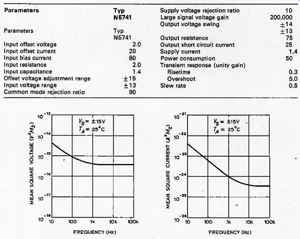
Fig. 1. Typical characteristics for a type 741 op-amp. (Courtesy Signetics
Corporation)
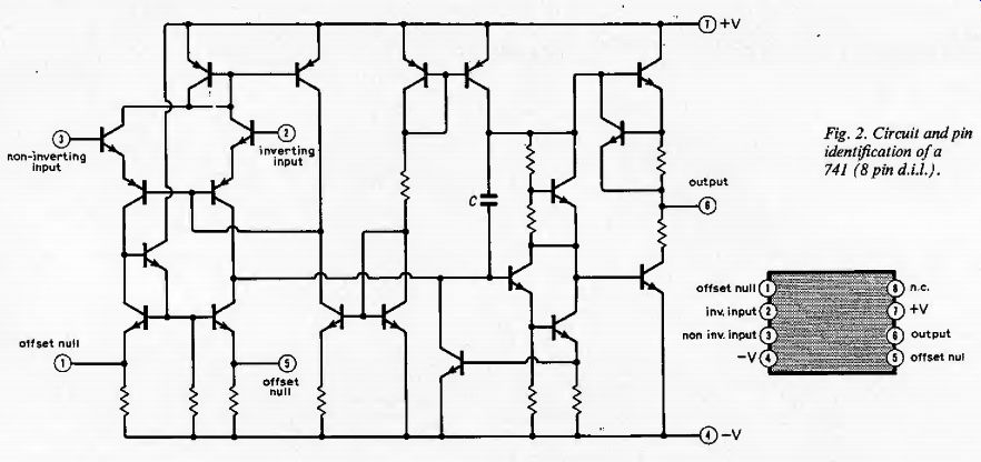
Fig. 2. Circuit and pin identification of a 741 (8 pin DIL).
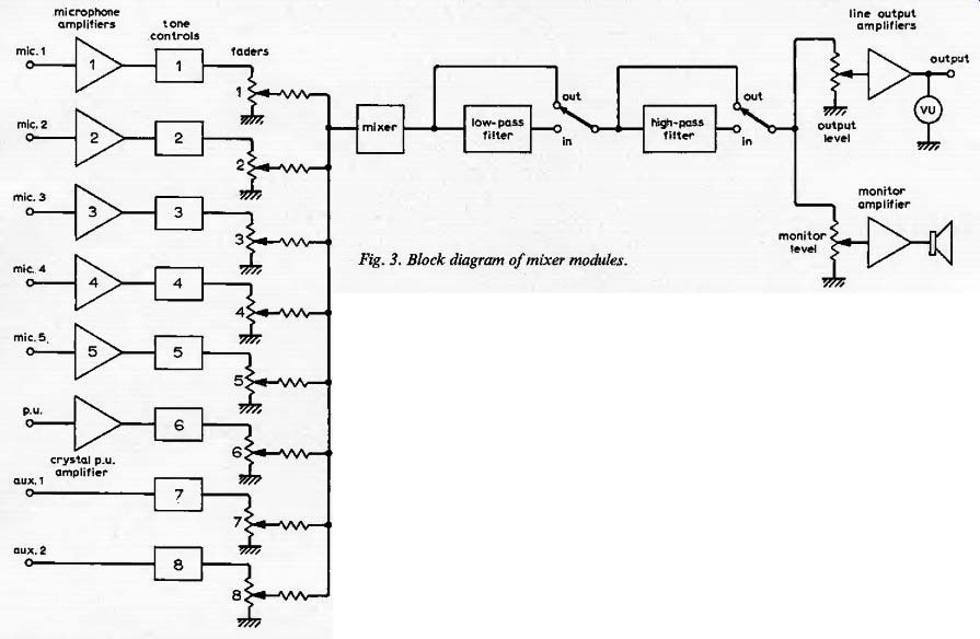
Fig. 3. Block diagram of mixer modules.
Noise considerations:
Once the decision has been taken on the grounds of cost and simplicity to use operational amplifiers of a particular type, then the user no longer has the very wide range of choices available to him in other designs.
Thus, where the absolute minimum of input noise is the most important factor in the design, it would be necessary to revert to one of the excellent designs published in this field by other authors. Alternatively, the same system could be adopted but using an operational amplifier of higher cost specifically designed for low-noise input performance. That is not to say that the present circuit has poor noise performance, as is seen from Fig. 1 which gives the characteristics of the type 741 operational amplifier. The input noise voltage and currents given are only typical figures, and where optimum performance is required at the input, a further advantage of using the same active device throughout becomes apparent: the user may simply interchange the operational amplifiers at the input until the unit with the minimum noise performance is found. This has not proved to be necessary in practice with the mixer system as described, since it has met ail the requirements of the user without selection. The very stringent processing techniques called for in the production of such operational amplifiers generally results in transistors at the input whose noise performance is markedly superior to the run-of-the-mill transistors of but a few years ago and should be adequate for all but the most demanding of users.
Two other key properties of the system over which control might appear to be less possible are the distortion and frequency response characteristics. Fig. 2 shows the circuit diagram of the operational amplifier used, type 741, which is now the standard operational amplifier for the majority of routine industrial circuits, though of course the integrated circuit manufacturers are continually producing newer i.c’s of ever-increasing performance. This particular operational amplifier is offered by nearly every manufacturer under different code numbers although usually the numbers 741 appear somewhere in the code. The same circuit is produced in a variety of packages: flat pack, TO-5, 14 pin dual-in-line, 8 pin dual-in-line, etc. The circuit is also produced to various specifications which sometimes follow from the packaging process, such as the temperature range which they will withstand, while in other cases a selection procedure picks out units with the lowest input current, widest voltage range, etc. The particular versions used in this mixer system were the lowest cost, unselected, 8-pin, dual in-line plastic package version, some of the main characteristics of which are shown in Fig. L1 The open-loop gain of the amplifier at low frequencies is greater than 100,000, resulting in a very high stability of gain even for feedback that still leaves the closed loop gain as high as 1,000 or more. When, as is often the case in audio systems, the gain of each stage may be 100 or less then the stability of that gain depends only on the stability of passive components At higher frequencies die picture is different. Because the amplifier is designed to be stable and free of oscillations with feedback of up to 100% then great care has to be taken in the control of the frequency response of each stage within the amplifier. If at any time the phase shift around the loop reaches 180° then feedback intended to be negative becomes positive and if the loop gain is still above unity self-sustaining oscillation will result. This explains the presence of capacitor C in the circuit of Fig. 2, This capacitor is connected at a critical point in the circuit where the impedance is relatively high, and ensures that the gain of the amplifier has fallen to a very low level before the frequency is reached at which the phase shift in the other stages becomes significant. Thus, at no time does the total phase shift of the amplifier approach 180° before the gain has fallen below unity. To achieve this effect the reduction in gain begins at a very low frequency so that the gain is reduced by a factor of 100,000 before the critical frequency is reached; i.e. the cut-off frequency for the open loop condition is of the order of 10Hz.
In a system in which there is only a single dominant high frequency time constant the gain-bandwidth product remains constant for all values of the feedback. A resistive feedback network that reduces a low frequency gain from 100,000 to 10 will roughly increase the upper cut-off frequency from 10Hz to 100kHz. Broadly speaking, with amplifiers of this type gains of up to 100 in each stage may be achieved with no serious attenuation in the audio frequency band. In the particular circuits used in this mixer the gain per stage is typically < 100 and a bigger problem is that of restricting the high frequency performance from a noise standpoint.
The output stages of a 741 operational amplifier can be seen from Fig, 2 to be a form of Class-B push-pull. Without feedback the resulting cross-over distortion would be serious, but, as explained above, the feedback is usually heavy and the feedback is correspondingly reduced. This is not the full story; at higher frequencies the reduction in open loop gain makes the feedback network less effective in reducing distortion and it would not be an ideal circuit for obtaining large output swings at frequencies above 100kHz, certainly not with light feedback. Direct measurements on the amplifier are discussed later and it will be seen that it meets most audio requirements with ease, though once again it must be stressed that the very highest quality amplifiers specifically designed for this application should be capable of better performance. The very low cost of the 741 operational amplifier means that competing systems are likely to suffer a heavy cost penalty for any significant improvement in performance.
System requirements
To meet the needs of the audio-visual aids department concerned, the system as shown in block diagram form in Fig. 3 was devised.
The specifications it was intended to meet are shown in Table J. Each of the eight channels was required to have separate bass and treble, Sift and cut tone controls, five of the channels being microphone amplifiers, one from a ceramic pickup and two line inputs receiving signals from tape recorders and the like. A line output stage was required capable: of operating into 600 ohm, although generally operating into a higher impedance. A monitor amplifier of 1-3W output was also included. To cope with signals having an excessively high or low frequency content, it was decided to have both a low-pass and a high-pass filter and to make these with widely-variable cut-off frequencies. This solution was adopted because the system, of which this mixer was to form a part, was still in the process of considerable expansion and the precise, requirements were, not known. All of the circuits described so far were based on the 741 operational amplifier but, at a later stage, a VU meter was added and this uses the only separate transistor in the system: Figs. 4-13 show the circuit diagrams of the various functional blocks included in the system. The only components not shown in these figures are the coupling capacitors C4a and C4b which connect the two line input channels to. their respective tone control circuits. A fuller discussion of the component values used in the mixer and the reasons for their choice are given in the following sections.
---------------
Table 1
Specification for c.c.t.v. audio mixer
Frequency response
Flat response from 30Hz to 20kHz
Hum noise 70dB below rated output
Input noise 200-Ohm source, 120dB below 1 volt.
Channels
Eight inputs :as follows:
(a) Five mic. Input
(i) Source impedance 50 to 500-Ohm.
(iii Source e.m.f. 0.125 to 0.28mV.
(b) One tele-cine (i) Source impedance 8 Ohm (or 16 Ohm). (ii) Source e.m.f. 500mV.
(c) One record player (i) Source impedance high.
(ii) Source e.m.f. 100 mV.
(d) One tape-recorder
(i) Source impedance 15 Ohm.
(ii) Source e.m.f. 100 mV. Tone control
To be provided on all input channels.
Bass + 10dB; treble +10dB.
Outputs (a) (i) to input of video recorder; unbalance impedance bridging for 600-ohm line, or (ii) 0.5mV into 200-Ohm. (b)
To supply 3-W loudspeaker.
VU meter
To be provided on output fa).
Type of controls
(i) Slider-type potentiometers for volume control,
(ii) Rotary-type potentiometers for bass and treble.
Console dimensions
Dependent on the case or cabinet available, but the operational position of control surface to be 30° to the horizontal.
Power supply 240V. 50Hz
-------------------
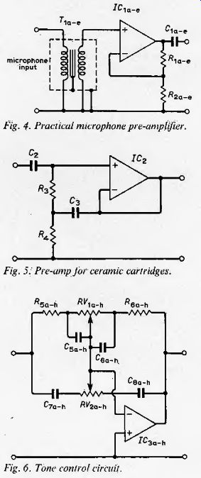
Fig. 4. Practical microphone pre-amplifier.

Fig. 5. Pre-amp for ceramic cartridges.
Fig. 6. Tone control circuit.
-----------------
Input amplifiers
The low output impedance and low voltage generated by high quality microphones is in conflict with the input characteristics of the operational amplifier. If the noise properties are to be optimized then the effect of both noise current and noise voltage must be investigated. The noise voltage of a typical 741 amplifier over the audio band is about 3. microvolts. Since the voltage generated by a microphone might be as low as a few tens of microvolts, the signal-to-noise ratio for direct connection would clearly be poor. If we note that the noise current, however, is of the order of 20 pico-amp, then we see that its contribution to the total noise, depending as it does on the low resistance of the microphone input combination, is small. It is this which forces the use of a microphone transformer upon us.
From a purely electronic standpoint, there would be much to be said for using a microphone with a high resistance obtained by winding a larger number of turns. A microphone with an impedance in the range 50- 500 ohm may be used with a transformer of step-up ratio 5-50 such that the impedance presented to the input of the amplifier is of the order of thousands of ohms, or higher.
The step-up ratio ensures that the voltage presented to the amplifier input terminals is now much greater than would have been the case for direct connection. Hence, the input noise voltage is less significant, but the input current is now flowing through a greater source impedance and is more significant. For any given type of amplifier there will be an optimum turns ratio which ensures that the contribution of noise due to voltage and current is comparable. For any other turns ratio, or variation in microphone impedance, the reduction in equivalent noise due to either voltage or current will be less than the increase due to the other. It does not follow that the ratio which is optimum from a noise standpoint will also be the optimum ratio for extended frequency response. For example, if the turns ratio is too high the effective source impedance of the microphone may be such that capacitive effects cause a fall in the upper cut-off frequency while it may be difficult to maintain a sufficiently high inductance to avoid losses at low frequencies.
The practical circuit used in this mixer is shown in Fig. 4. For a typical microphone resistance of 200 (mult. by 1.25 for USD ) £2 the 15:1 turns ratio of the transformer results in an equivalent source resistance of 45 k-O. It is tempting to select feedback resistors that give gain in this stage to eliminate the risk of noise pickup in subsequent stages, but this is inadvisable for two reasons. Firstly, the smaller the feedback the less is the input impedance of the amplifier raised, while it is important that the input of the amplifier should not place an excessive load on the secondary of the transformer. Secondly, it must be remembered that operational amplifiers of this kind are compensated internally to make them stable for all feedback ratios and hence the compensation reduces the gain-bandwidth product sharply. A low-frequency gain of 1000 is easily obtained, but the upper cut-off frequency might then fall well below 10kHz. With the component values indicated, the overall voltage gain from the microphone to the output of this stage is well in excess of 100. The output voltage thus obtained is of the order of a few tens of millivolts and is comparable to that expected at the line inputs.
For gramophone use the mixer was intended to operate from a ceramic cartridge and a high input impedance is required.
The circuit of Fig. 5 provides this with a voltage gain of unity since the output voltage of the cartridge is already equal to or greater than that of the preceding cases. As such a cartridge does not provide a DC path for the amplifier input current, it is necessary to provide such a path as with resistors R3 and J?4. These would provide a load resistance for the cartridge which would result in: a poor low-frequency response, since the cartridge impedance is capacitive. The center tap of the resistors is therefore bootstrapped from the output of the amplifier by capacitor C3. This ensures that the p.d. across R3 is very small and hence that the current through it is negligible, corresponding to a very high dynamic input impedance.
Much has been written recently about alternative input stages for ceramic pickups but there is some advantage to retaining at least one input of this form which may accommodate any voltage source including those of high internal impedance.
Tone controls. The Baxandall tone control is standard within high quality amplifier circuits [2] and meets all the requirements of the present unit (Fig. 6). Since there was to be additional voltage gain in the following, mixer stage and in the line output unit, the resistor values in this stage were chosen for a mid-band gain of unity. The intended input voltages are of the order of a few tens of millivolts, i.e. well above noise level, while leaving a very large overload margin. In an attempt to reduce the component count as low as possible, advantage has been taken of the almost zero DC output voltage of the amplifier by omitting the electrolytic capacitor that would normally be used between stages. Since the overall voltage gain from the input of the tone control circuit to the line output is little more than 30 and the equivalent input offset voltage is but a few millivolts, the line output offset is very much less than 1V. This must be allowed for if DC coupled into the load but is not of sufficient magnitude to contribute anything to the non-linearity of the output stage. It is in such modifications as this that the inherent balance at the input of an operational amplifier combined with its large dynamic output range allows for such simplifications.
Only experience will show whether the small amount of DC voltage that remains across the gain controls will result in noisy operation.
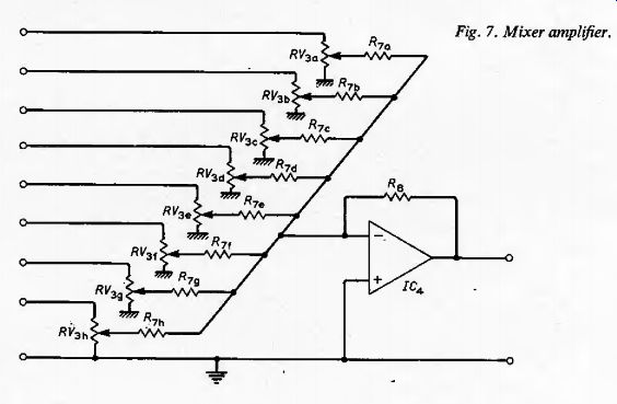
Fig. 7. Mixer amplifier.
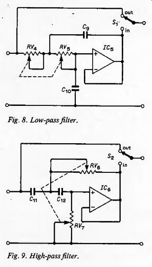
Fig. 8. Low-pass filter.

Fig. 9. High-pass filter.
Mixer stage
This is a conventional summing amplifier (Fig. 7) with an output voltage equal to about five times the sum of the input voltages. It would be perfectly possible to use this stage for line output functions, if necessary increasing the gain of the stage as appropriate. As the equipment was at the experimental stage, it was decided to include high-pass and low-pass filters of variable cut-off frequency to be switched in or out as required. It then became advisable to follow these with a final line output stage which also contributed voltage gain. Since no individual stage was called on to provide a high voltage gain, the bandwidth easily exceeded the specification of 20kHz.
Low pass filter. The circuits used for both this and the following filter (Fig. 8) are standard in industrial practice, making use of the operational amplifier in its unity gain mode, i.e. as a voltage follower. The filter has a second order response with cut-off frequency controlled by the ganged variable resistors in the range 500Hz to 20kHz. This range is clearly wider than would be required for audio applications alone, but it was felt that the availability of the filter for experimental demonstrations might be worth while. For this, as with the preceding circuits, the output impedance is low, partly because of the low output impedance of the amplifier itself, and partly because of the heavy negative feedback.
High pass filter. This function is simply obtained from the previous circuit by interchanging resistors and capacitors (Fig. 9). Once again the cut-off frequency, in this case a lower cut-off frequency, is variable over a wide range and was chosen to be from about 10Hz to 5 kHz.
Monitor amplifier. The increasing availability of low cost integrated circuit power amplifiers greatly simplifies the job of the audio designer. Advantage was taken of the amplifier module type EA1000 (Fig. 10) since this fulfilled all the requirements for this unit The supply voltage needed was a single-ended positive supply of some 20V and the circuit operates from the smoothed, but unregulated, supply from which the + 15V regulated supply is also derived. On load this supply falls from an initial value of 24V to 21V with a peak output power of 2-3W. At lower powers the distortion of the amplifier is more than adequate and the frequency response, particularly at high frequencies, is very good. The sensitivity of the amplifier is such that it can be used directly from the ceramic pickup and the excess gain is, in this application, almost an embarrassment and explains the need for the additional 1-MO resistor in series with the monitor gain control. For the given value of supply voltage the load resistance should be 15 Ohm.
Fig. 10. Monitor amplifier.
Fig. 11. Line output stage.
Line output stage. This is basically similar to the mixer (Fig. 11), consisting of a virtual earth amplifier preceded by a gain control.
Since the integrated circuit used has current limiting, no damage should occur either to the amplifier or to external circuits under any short term fault conditions. Alternative values of R10 may be used if the sensitivity range provided by RV9 is not suitable for particular applications. The 600 Ohm resistor R10a was included to provide matched operation with a video tape recorder but may be omitted if a lower output resistance is required.
VU meter. (Fig. 12). Lack of experience with the meter circuits of this type led the authors to adopt a circuit described in a recent article. It is the only circuit in this unit that uses a transistor and performs admirably. Again, replacement by an operational amplifier might lead to some economy in bias components but this is presumably one circuit where a high open-loop gain is less necessary. The VU meter directly monitors the line output which, because of the relatively high supply voltage, might cause overloading of the meter in some cases.
-- Edge connector wiring details
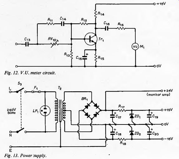
Fig. 12. V. U. meter circuit.
Fig. 13. Power supply.
Power supply. This is entirely conventional (Fig. 13) providing a nominal ± 15V for the operational amplifiers and +15V for the VU meter circuit. The. positive unregulated output is used for the monitor power amplifier, the open-circuit voltage being 24Y with the components used. With a continuous sinewave output, just short of clipping, in the power amplifier this unregulated output falls to about 21V, leaving an adequate margin for the operation of the resistor-zener diode stabilizer.
Since each operational amplifier typically consumes less than 2mA--the exception is the line amplifier when driving into a low load resistance-the standing current in the zener need not be high. A simple regulator of this kind seems adequate in view of the excellent rejection of line voltage variation offered by the operational amplifiers. Even on the most sensitive inputs, a total hum and noise of 60dB below the signal level, was achieved.
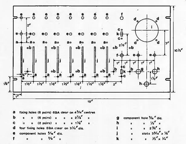
Fig. 14. Front panel layout.
Construction
The mixer was to be incorporated in a combined audio/video control-room console, which led to a requirement that the. overall width of the mixer should not exceed about twenty inches. A standard 19 in panel carrying all components was used to meet this requirement.
The controls to be accommodated at the front of this panel consisted of eight linear-motion faders, twenty rotary-motion potentiometers, two slide switches and a mains on/off switch. The VU meter, a mains fuse and a neon indicator were also required to be mounted on the front of the panel. The rear of the panel carried a sub-chassis for the power supply, brackets for the input and output sockets, monitor amplifier and input transformers, six edge connectors for the printed circuit boards and a printed circuit board for the VU meter circuit.
Such a large number of front panel components required that a compromise be made between the separation of controls,, for ease of use, and the length of the wired interconnections, to reduce noise and crosstalk. The resulting front panel layout (Fig. 14), shows that, the tone controls and fader for each channel are in vertical alignment and that this approach leads itself to modular construction. The common apparatus in the system is all mounted to the right of the panel, allowing the tone control .and fader components for the desired number of channels to be added to the left.
The tone control and input circuit components were mounted on commercially-available printed circuit boards carrying power supply distribution tracks for the integrated circuits. Each board carries all the components for two channels and is mounted in a 24-way edge connector located between the faders. The high-pass and lowpass filter components were mounted on a single board, and the mixer components were accommodated on a separate board.
These two boards were of the same type as those used for the tone control circuits, and were mounted in the same manner. A printed circuit board was designed to carry all the components in the VU meter circuit so that it could be mounted directly on the pins at the rear of the meter.
The power supply and mains plug were supported on a small sub-chassis raised above the output volume controls and mains switch by means of pillars. The line output socket and monitor loudspeaker socket were fixed to a single bracket supported by the bolts holding the mixer and filter edge connectors. The monitor amplifier printed circuit board was fixed to the other mixer-board pillar by means of a simple bracket. The eight input sockets and five input transformers were mounted on a single bracket running along the front panel below the faders.
Most of the wired interconnections were made by means of 8-way, unscreened, twisted cable running underneath the bracket carrying the input sockets and transformers.
Screened pairs were found to be unnecessary, the only screened wire being a 3-in length between the line output volume control and the high-pass filter output. The edge connectors need to be raised from the front panel by small pillars to allow a clearance for the wiring pins. The wired interconnections can easily be made by fixing the edge connectors in the inverted position during construction and then restoring them to the correct position when the work is completed.
Results
Appendix 1 gives a comprehensive picture of the behavior of the system and should allow the individual to use whatever combination of the sub-sections is most convenient. Other amplifier/mixer circuits have been described having performance that exceeds that of the present unit. In most cases, however, the component count has been considerably higher with a corresponding increase in constructional costs. It is recognized that the component cost may not show the same advantage; this will clearly depend on the cost of the integrated circuits to the individual user. As in industrial engineering, the shortening of design time, the increased flexibility and the reduction of auxiliary components makes the case for integrated circuit operational amplifiers in audio frequency designs almost unanswerable.
by J. H. Evans,* Dip.Tech.{ Eng.} and P. Williams,* B.Sc. [ Paisley College of Technology. ]
Appendix I
Performance data
Line output
NOTE: All measurements made with R10=1-kO and R10a = 0.
(1) Line input auxiliary channel 1:
Tone controls: 3 o'clock.
Filters: out
Freq.: 1 kHz.
Reference level: 10mW into 600 ohm, i.e. +10dB.
Frequency response relative to above: + 0dB to --1dB at 5Hz and 20kHz.
Response sensibly flat to 40kHz --5dB
Attenuation at 100kHz --23dB Rise time iips.
Maximum power into 600 Ohm (un-distorted)
>50mW at 100Hz.
>50mW at 1kHz.
-40mW at 10kHz.
Output resistance at 1kHz, 1-Ohm
Tone controls
Bass:
+13.5dB
> 50Hz
-15dB
Treble; +13dB
-15dB
Filters
For 30dB attenuation at 10Hz and 50kHz.
3dB bandwidth is 50Hz-14kHz.
Filter cut-off frequency range
Low-pass (scratch) filter ~ 500Hz-20kHz
High-pass (rumble) filter ~ 10Hz - 5kHz.
Distortion
Output + 10dBra into 600 Ohm.
(a) Frequency 1kHz: 2nd harmonic < -65dB
3rd harmonic < --64dB
4th and higher harmonics--not measurable.
Total harmonic distortion ~0.04% (including test oscillator distortion).
(b) Frequency 100Hz:
Total harmonic distortion -0.04%.
[...]
------
References
1. Signetics Corporation, 'High Performance Operational Amplifier Linear Integrated Circuit, Type N5 741V, August 1970.
2. Quilter, P. M., 'Low Distortion Tone-Control Circuit', Wireless World, April 1971, pp. 199-200,
3. Walker, H. P., 'Stereo Mixer', Wireless World, June 1971, p. 298.