Foil antenna array hidden by wallpaper
by Ray Schemel and Dennis Brown
For FM stereo, long-distance TV, or improving reception in marginal areas, one's first temptation is to install the largest and most elaborate fish bones, wire mesh reflectors, and other pieces of aluminum-mongery at the highest and most eye-offending part of a house. It is odd, but more time, effort, and money is expended on extracting the last decibel of gain from an antenna than almost any other part of the receiver chain.
After six months' exposure to the weather, those precious decibels may welt have been lost and the extra signal level might better have been obtained, for example, by paying attention to the antenna matching. In fact an excellent location for an antenna could well be in the same room as the receiver — it goes without saying that the room should have walls of paper and be in the attic! The antenna structure is not exposed to the elements, water cannot enter the feeder, feeder losses are minimized, and the appearance of our towns and villages would be much improved.
The "walltenna" was conceived as a method of receiving the Wroth am and Norwich FM transmitters at a location near the coast of Holland at distances of 180 and 135 miles respectively. At. this range the transmitters are well below the normal horizon, but a weak signal is almost always present/Signals from the "walltenna" fluctuate over a wide range, and in good weather conditions, presumably when sufficient refraction or ducting takes place, stereo reception is perfectly possible. Estimates of quality tend to be very subjective, but the signal is well above a significant degree of quieting for a high proportion of the time, although not necessarily of entertainment value because of the rapid fading. The estimates are quoted, not because this article is about FM reception, but to give some idea about the pick-up properties of the finished antenna.
The basic principle behind the antenna is simple. Why not make a large array essentially two dimensional, and then hide this behind wallpaper or some other decorative medium? The large size of the array would compensate for the losses of the walls, and the bother of mounting antennas on the roof would be avoided. Various alternative schemes were considered, including multi-element Yagi and rhombic arrays on the ceilings and floors, but the arrangement described here was found to be the most suitable because it was not overly directional in the horizontal plane.
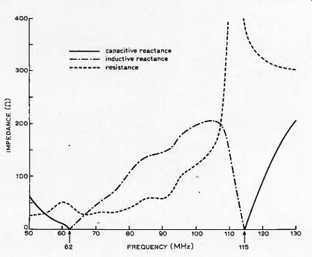
Fig. 1. Series impedance of 1.5 meter dipole mounted on
a wall (measured values).
It consists of a vertical array of dipoles mounted broadside to the direction of propagation; the greater the number of dipoles, the greater the signal pick up. It is often overlooked that the signal power extracted from a given field strength is broadly independent of the wavelength, being only a function of the area of the antenna. An elaborate 20-element beam used for UHF TV probably picks up less power than a piece of wire connected to a medium-wave radio. To increase the power available one has no real alternative but to use the largest capture area practicable.
A dipole in free space is resonant when it is almost one half wavelength long. It then has a gain of about 2.2dE relative to isotropic. As the length is increased, the familiar figure-of-8 polar diagram narrows, and when the dipole is a full wavelength long and is center fed, the gain increases by a further 1.5dB. Of more importance is that the antenna is inherently a good radiator (or receiver) as the length increases beyond a half wavelength.
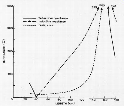
Fig. 2. Series impedance of a dipole mounted on a wall at 92MHz (measured
values).
Four such dipoles, suitably phased, could give a gain of up to 10dB, and if one were fortunate enough to be able to place a plane wire mesh reflector behind the dipoles, the gain could go as high as 16dB, not allowing for mutual coupling losses, A reflector is scarcely possible in a living room, but even so, a gain of up to 10dB is quite promising. Four dipoles fit nicely into an average height of living room, and so this particular design was adopted. In practice the gain will depend on the wall characteristics.
The situation when dipoles are placed adjacent to a lossy wall is complicated in that the impedance and the resonant frequencies are markedly altered. The resonant frequency is always decreased, and the radiation resistance is also altered for a given electrical length. In addition, radio waves must penetrate what amounts to a lossy dielectric.
Reflection and refraction occur at each wall-air interface and attenuation occurs in passing through the brickwork. Complicated conduction and displacement currents are set up in the wall. In spite of this, the signal pick up properties of the antenna are not necessarily degraded provided that full account is taken of the changed impedance of the dipole. Fig. 1 shows the impedance of a 1.5-meter dipole mounted on an 18-in thick breeze block and brick wall. The antenna was made of 1.5-in wide aluminum foil taken from a capacitor, and would normally be resonant at about 97MHz in free space.
Notice that the half-wave resonance has shifted to 62MHz and the full-wave resonance occurs at 115 MHz. An alternative measurement is shown in Fig. 2, where the frequency is held constant at 92MHz and the length of the dipole is varied. In this case the dipole was placed along an 18-in thick reinforced concrete beam; notice again the length at which the half and full-wave resonances occur.
Most readers will not have the facilities for measuring antenna impedances, which in any case vary in a complex manner with frequency and with the type of wall. Fortunately, it is not necessary. An antenna does not have to be resonant, and neither does it have to be any particular length.
Provided that it is long electrically, i.e., greater than, say, one half wavelength, and that some suitable impedance matching to the receiver is performed, it will exhibit reasonable pick up properties. A good rule of thumb is to make an antenna a full wave-length long. It then yields useful gain and is not too directional or large in size. For average brick walls this corresponds to it being about one half wavelength long in free space.
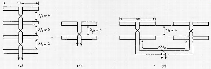
Fig. 3. Four vertically-stacked dipoles (a) most convenient for average
living rooms; alternatives are (b) and (c). Electrical lengths of feeders
shown.
Constructional details
The configuration of four vertically-stacked dipoles referred to earlier will be found the most convenient for an average eight-foot living room. Details of this are shown in Fig. 3(a), and its construction is largely self-explanatory except for the feeders. Figs. 3(b) & (c) show other arrangements which may be found more suitable, and in these cases the general rules for combining any number of elements are as follows:
When n/2 wavelengths of feeder are terminated in an impedance Zr, the input impedance of the feeder is also Zr. The signal is shifted in phase by 180 degrees. Usually n = 1.
Balanced feeders can always be reversed to give a fixed phase shift of 180 degrees.
When (n/2 + 1/4) wavelengths of feeder are terminated in an impedance Zr, the input impedance of the feeder is Zz
0/Zr, where Z0 is the characteristic ..impedance. Usually n = 0.
When dipole elements are not mounted above one another, there is a relative phase shift caused by the difference in time of arrival of the received signal. The phase difference is 360 Dsin0, where D is the antenna spacing in wavelengths and G is the angle of arrival relative to the line joining the elements.
The phase difference of two groups of dipole elements may be compensated for by using unequal feeder lengths, provided that the sum length of both feeders is n/2 wavelengths.
The electrical length of feeders is longer than their physical length.
Because of this, the phase shift is 360/v degrees per wavelength of feeder, where v is the velocity, factor.
Dipoles should be spaced no closer than a quarter of a free-space wavelength apart, otherwise mutual coupling effects reduce the potential signal pick up.
An excellent material for the antenna is the foil from large paper or electrolytic condensers. Aluminum baking foil or one of the proprietary aluminum-backed wallpapers can also be used. The width is not critical, but to make the antenna reasonably wide band, it should be 2in of more. After cutting the foil it may be. pasted directly onto the wall, leaving a small amount free at the center for making connection to the feeders.
Feeders present a small problem if they are to be invisible. A surprisingly low-loss feeder suitable tor the purpose of VHF can be made from aluminum foil and ordinary newspaper. Lay a long strip of aluminum foil on a flat surface and tape down the ends. Then paste a similar width of newspaper onto the foil.
When it is dry, lay two lengths of thin wire, say 36 to 40 s.w.g., along the middle of the newspaper about 0.25 in apart, and tape down the ends. Finally, paste a second strip of newspaper on top to hold the wires in position.
Alternatively, those who are a little more adventurous could try dispensing with the top layer of newspaper and instead building up the feeder directly on the wall.
A feeder made in this way had a velocity factor of 0.5 and an impedance of 170 ohms, but these figures will be dependent on the dielectric constant of the paper used. For short runs of feeder, say up to one wavelength, the approximations involved are not likely to give significant effects, but to remove the uncertainty connected with the velocity factor it is hoped that a manufacturer will be found to produce a standard type: of strip line. There are other alternatives: ordinary screened balanced 75-ohm feeder can be channeled into the wall, or unscreened twin feeder can be. placed in plastic conduit.
Connect feeders to the antennas by bending over the aluminum foil, pressing down firmly over the join and then folding a second time at 45° to the first, and finally placing adhesive tape over the join to hold the foil in position.
The special feeder described above is only required down to the skirting board, and for convenience it should be made an integral number of quarter wavelengths long if possible. At the skirting board it should be matched into ordinary coaxial cable or a balanced feeder.
The impedance matching makes use of a pi network and a balun as shown in Fig. 4 (the balun is not required if the receiver has a balanced input). To obtain the maximum range of adjustment, inductance L1 should be wound on a former that accepts brass and ferrite slugs. Also, some obstinate antennas may still need additional encouragement to match, in which case an extra quarter wavelength of feeder can be inserted on the receiver side to give a further impedance transformation. The pi network could, with advantage, be placed on the unbalanced side of the balun as it makes the two adjustable capacitors earthy on one side. However, 3-30pF trimmers are easy to obtain whereas ones four times this value are not, and the balun always works at the correct impedance level.
Baluns are available but you may wish to make your own. A satisfactory balun can be made by winding 10 turns of bifilar wire onto a coil former, about Viin diameter with a ferrite slug. The two windings are then placed in series as shown in Fig. 4.
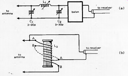
Fig. 4. Impedance matching unit (a) requires a balun (b) for receivers with
unbalanced input circuits. L1 is 5 to 10 turns on a 0.25 in dia. former about
0.3 in long. L2 is 10 turns of close-wound bifilar wire on 0.25in dia. former
wire gauge can be around 28-30 s.w.g.
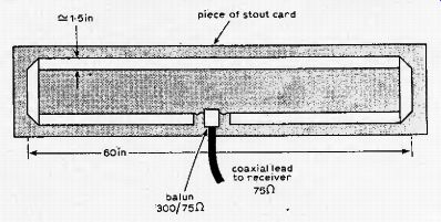
Fig. 5. Temporary antenna is used to find best position on wall.
Measurements and setting up
Before constructing the "walltenna", make a folded dipole as shown in Fig. 5, remembering to include a balun. This is most important, as unscreened twin feeders can pick up appreciable amounts of signal which may upset measurements. If the receiver normally operates with a balanced input it is well worth using a twin screened feeder to overcome the pick up problem, or even considering the use of two baluns and ordinary coaxial cable. The temporary antenna should be moved to different points on the wall to find the best positions, and these should be used for the finished dipole elements.
After the antenna is finished, the pi network will require adjusting for maximum signal transfer. To do this a meter is really required, perhaps placed on the AGC line of the receiver, but an acceptable alternative is to use a weaker station and to tune for minimum noise on stereo. First adjust C2, then L2, and finally C1. Remember that C2 and C1 are live as far as the signal is concerned and must not be touched, as opposed to adjusting, when measuring.
If the antenna of Fig. 3(c) is being used, the tapping point along the feeder must first be optimized. This can be done by calculation; the displacement from the center point away from the dipole nearest the transmitter is ½ Dvsin (theta) as per the points made earlier. Alternatively, a temporary sliding connection can be made along the feeder and then this is adjusted together with the pi network.
Follow the above procedure before wallpapering, because, in spite of its simplicity, difficulties which cannot be rectified afterwards may occur. In principle, every element added to those existing should increase the total signal, after an impedance adjustment has been carried out. In practice it may be found that adding further elements gives no increase or even a decrease in signal, and better results are obtained by reversing the feeder connections. Such effects need not be unexpected. They result from differences in the pick up capabilities of each array element and the variable impedance of the wall. In these cases it is simply a question of cut and try methods, and if ail else fails, of experimenting with fresh positions.
The "walltenna" principle is applicable to a wide variety of antennas and it is hoped to be able to give constructional details for u.h.f, TV at a later date.