Practically all current-model fm tuners are transistorized, although many tube-type tuners are still in use. Many fm tuners are combined with AM tuners in combinations; quite a few fm tuners are merchandised as separate units for hi-fi buffs. The superheterodyne configuration is universal; however considerable variation of detail is employed. For example, lower-priced fm tuners use a single transistor as a combined oscillator and mixer (converter), whereas deluxe type tuners provide separate oscillator and mixer transistors. Again, economy-type designs generally utilize ganged tuning capacitors (Fig. 2-1), while the more elaborate designs provide permeability-tuned arrangements (Fig. 2-2). Solid state designs are based on the transistor-for-tube principle, except for systems employing IC packages.
Fig. 2-3 shows a block diagram for a typical fm tuner. This arrangement includes six transistors, two ratio-detector diodes, an afc diode, and an AGC diode.
Only the RF stage is agc-controlled. The afc circuit minimizes the effect of any frequency-drift tendency in the oscillator section. No limiter is provided, because a ratio detector has self-limiting action. Nearly all fm tuners have a stage of RF amplification (pre-selection). This provides improved input selectivity, with the result that the possibilities of cross modulation and image interference are minimized. To ensure that cross modulation will not occur in the RF stage when high-level adjacent-channel signals are present, AGC control is provided.
Common trouble symptoms caused by defects in fm tuners are as follows:
1. No fm reception.
2. Weak and/or noisy output.
3. Poor sound quality.
4. Afc failure.
5. Co-channel and adjacent-channel interference.
6. Incorrect dial calibration.
7. Intermittent operation.
GENERAL DISCUSSION
An fm broadcast signal is basically a high-fidelity transmission, whether the mono or the stereo mode is used. Note that some fm broadcast stations also transmit a multiplexed subsidiary carrier-assignment (SCA) signal; this is not a high-fidelity transmission.
An SCA signal cannot be reproduced by a conventional fm receiver; in fact, traps are provided to eliminate any possibility of SCA interference. An fm signal not only provides better sound quality than an AM signal, but it also provides quieter reception in normal operation. That is, natural and manmade noise is chiefly an AM disturbance, to which fm receivers are largely unresponsive. The high-fidelity capability of an fm system is due to its comparatively wide channels (see Fig. 2-4). Each fm broadcast channel has a bandwidth of 150 kHz, or ±75 kHz.
Although a high-fidelity fm signal can be transmitted in a narrower channel, wide channels provide a better signal-to-noise ratio.
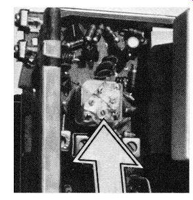
Fig. 2-1. Arrow points to gang tuning capacitor.
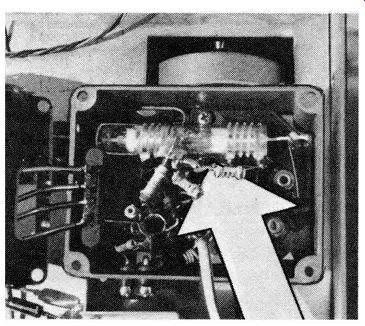
Fig. 2-2. Arrow points to permeability-tuned RF and oscillator coils.
It follows from Fig. 2-4 that an fm receiver should have a bandwidth of 150 kHz. The fm broadcast band extends from 88 to 108 MHz, encompassing a total range of 20 MHz; an fm station occupies (including its guard band) a range of 200 kHz. Thus, a maximum of 100 fm broadcast stations can be accommodated in a given service area. Co-channel interference from distant areas is much less troublesome in the case of fm, than for AM. This comparative immunity of an fm receiver to co-channel interference is due to the "capture effect," which means that the stronger signal tends to suppress the weaker signal.
If one signal is twice as strong as the other signal, the suppression is practically complete. Even if one signal is only 50 percent stronger than the other, the suppression is very effective, provided that the receiver is in good adjustment.
All fm receivers use an intermediate frequency of 10.7 MHz. At the 50 percent of maximum response points (6 dB down) on the IF response curve, the bandwidth is typically 200 kHz, as shown in Fig. 2-5.
The comparatively high value of intermediate frequency reduces the circuit complexity that is required. For example, if a lower intermediate frequency were used, such as 455 kHz, elaborate circuitry would be required to obtain a flat-topped response over a bandwidth of 150 kHz. When the bandwidth of an amplifier is increased, its gain is decreased. Therefore, the IF stage gain is consider ably less in an fm receiver than in an AM receiver.
Therefore, an fm receiver employs more IF stages.
At least one more IF stage is provided in most tuners.
When two more fm IF stages are included, the last stage operates as a limiter; since a limiter is essentially an overdriven amplifier, its gain is considerably less than that of the other IF stages.

Fig. 2-4. Bandwidth specifications for commercial fm.

Fig. 2-5. Frequency response of an IF amplifier in a typical fm tuner.

Fig. 2-3. Block diagram for a typical fm tuner.
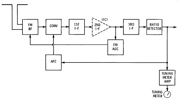
Fig. 2-6. Block diagram of an fm tuner using an integrated circuit.
Some fm tuners employ integrated circuitry, as exemplified in Fig. 2-6. As noted previously, a typical IC package has 10 terminals, with normal operating voltages specified. We often find groups of two terminals, or groups of three terminals tied together in an IF configuration. When an IC section develops a defect, the terminal voltages become abnormal in most cases. This situation is analogous to abnormal terminal voltages for a defective transistor. The receiver service data will usually specify the normal DC current demand of an IC package, such as 6 mA. Therefore, a current check can be made in addition to voltage checks. Technician apprentices must be on guard to avoid confusion between IC defects and leaky capacitors. That is, a leaky capacitor connected to an IC package terminal can make the IC "look bad." Therefore, we check capacitors first.
Many hi-fi fm tuners include a tuning meter or a tuning indicator such as some form of electron-ray tube. In the example of Fig. 2-6, a zero-center meter is used as a tuning indicator. The meter is energized from the output of the ratio detector, and high sensitivity is provided by a transistor that operates as a tuning-meter amplifier. As the converter stage is tuned through the center frequency of the incoming fm signal, the output from the ratio detector swings from positive to negative. In turn, the pointer on the tuning-meter scale deflects from above center to be low center. The output from the ratio detector also energizes an afc diode (reverse-biased diode) to minimize converter frequency drift. A reverse-biased junction diode operates as a small capacitor, due to its junction capacitance. When the value of the re verse-bias voltage changes, the junction capacitance also changes. To avoid overload of the RF stage on strong incoming signals, an fm AGC circuit is provided; this minimizes the possibility of cross-modulation interference.
Fig. 2-7 shows the configuration for a typical transistor fm tuner. In this example, the fm AGC circuit is supplemented by a local-distant switch in the base input circuit of the RF amplifier. This is a desirable feature, because the base circuit is untuned, and cross-modulation can become a problem when strong incoming signals are present. In the "Local" position of the switch, substantial signal attenuation is provided by a resistive pad. Automatic frequency control is provided by diode X3, which is shunted across the oscillator tank. An afc defeat switch is included to facilitate tuning-in of weak signals; that is, if afc is used while attempting to tune-in a weak signal, the oscillator will often sweep through the weak carrier too fast to lock in. As in nearly all fm receivers, a ratio detector is used because of its self-limiting action; some pre-limiting is also provided by R35 in the collector circuit of Q5.
Alignment Principles
Ratio detectors do not respond to amplitude modulation unless the modulation percentage is quite high, or unless the detector is defective or misaligned. The following general discussion will serve as a guide; however, the service data for a particular receiver should be read carefully before proceeding with frequency checks or alignment adjustments. An ac curate signal generator is basic; its output may be applied to the grid of the last IF stage. With reference to Fig. 2-8, an unmodulated RF signal is applied at A-B, and a VOM or VTVM is connected across R1.
Using a 10.7-MHz signal, the primary of transformer T is adjusted for maximum meter indication. Next, to check the secondary alignment, it is necessary to divide the load circuit into two symmetrical parts.
For example, we can connect two 100-k resistors (R2 and R3) across R1. A voltmeter is then connected from the junction of R2 and R3 to the audio output point (from Y to X1). Then, the secondary of the transformer is tuned for zero indication on the volt meter.
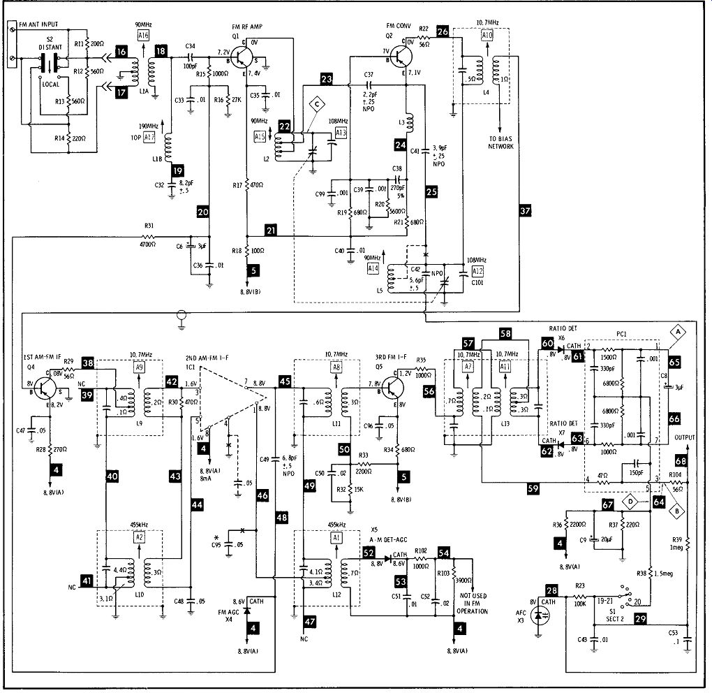
Fig. 2-7. Configuration for a transistor fm tuner.

Fig. 2-8. Ratio-detector circuit, showing modification for alignment.

Fig. 2-9. The fm sweep signal.
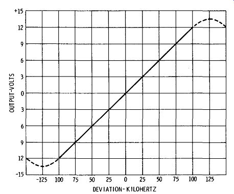
Fig. 2-10. S curve response produced by a normally operating ratio detector
circuit.
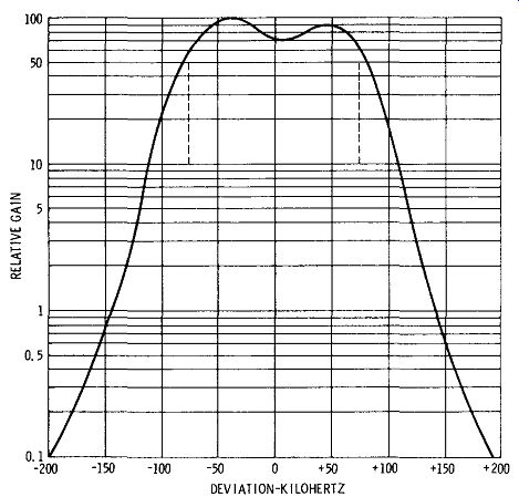
Fig. 2-11. Typical fm RF or IF response curve.
To check the IF alignment, connect the voltmeter across the load resistor of the ratio detector, and inject an unmodulated 10.7-MHz signal at the input of the mixer stage. Then, peak each IF stage for maximum indication on the meter. Finally, alignment of the rf, mixer, and oscillator (or converter) stages is similar to the procedure previously described for AM receivers; the only difference is in the higher frequencies that are used in aligning the fm stages. You will find that an oscilloscope and sweep generator are more practical for checking frequency response, be cause the bandwidth of the circuits is easily deter mined. To anticipate subsequent discussion, various trouble symptoms are caused by either subnormal or excessive bandwidth, although the center frequency of the stage is normal. Receiver service data will specify the connections to be used in sweep alignment. The basic considerations are as follows:
1. To check the center frequency and the band width of the response curve, accurate marker signals must be used. A marker signal produces a pip (birdie) on the curve at the frequency to which the marker generator is set.
2. Marker generators are crystal-calibrated to en sure maximum accuracy. The more elaborate types of generators will provide two or more markers simultaneously.
3. A conventional marker generator that provides a single marker is adequate, provided that it has good accuracy. The scale should also be reasonably expanded, so that it is easy to read frequencies such as 10.6, 10.7, and 10.8 MHz (see Fig. 2-5). The basic characteristics of an fm sweep signal are shown in Fig. 2-9. A normally operating ratio detector produces an S curve such as that shown in Fig. 2-10. An ideal response curve is perfectly linear for 100 kHz on either side of 10.7 MHz. Fig. 2-11 illustrates a typical RF or IF response curve for an fm receiver. Although the top of the curve is not entirely flat, the end result of limiting through the ratio detector is to effectively "slice off" the top of the IF curve, thereby changing the double-humped top into a flat top. The dotted lines indicate the limits of the fm signal swing, or deviation. Technician apprentices should observe that a single stage will always have a greater bandwidth than when it is followed by additional stages in cascade. It is the overall frequency response that determines the fidelity of the fm system.
Distortion Checks
After an fm tuner has been repaired and/ or re aligned, the final proof of performance consists in a measurement of the percentage of distortion.
This AUDIO OSCILLATOR FM SIGNAL GENERATOR FM TUNER HARMONIC DISTORTION METER

Fig. 2-12. Test setup for measuring percentage of harmonic distortion of
a tuner test requires an accurate fm signal generator and a harmonic-distortion
meter. If you wish to make distortion measurements at high and low audio
frequencies (at audio frequencies other than 1 kHz or 400 Hz), an accurate
audio oscillator will also be required. That is, fm signal generators provide
modulation at 400 Hz or 1 kHz, but do not provide for tests over the entire
hi-fi range from 20 Hz to 20 kHz. Fig. 2-12 shows the test setup that is
used. The audio oscillator externally modulates the fm signal generator,
which in turn drives the fm tuner-usually at a carrier frequency of 100
MHz. The output from the fm tuner is fed to the harmonic-distortion meter,
which indicates the percentage of distortion that is present.
As noted previously, the audio oscillator and the signal generator should have less than 1 percent distortion, in order to make a valid test of a hi-fi tuner.
Fig. 2-13 illustrates a typical fm signal generator.
If the percentage of IM distortion is to be measured, the fm signal generator is externally modulated by the two-tone signal output from the IM analyzer. In turn, the output from the fm tuner is fed to the input of the IM analyzer. Of course, the harmonic distortion or the intermodulation distortion of the hi-fi system can be measured, if desired; if the total distortion percentage is tolerable, there is no need to measure the distortion percentage for the fm tuner by itself. On the other hand, if the total distortion percentage is out of acceptable limits, it becomes necessary to track down the major source of the distortion. In this situation, we need to make a measurement of the distortion percentage produced by the fm tuner.
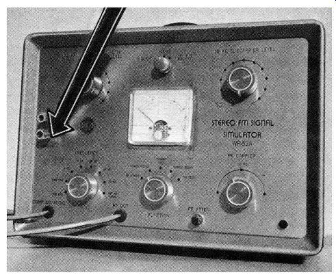
Fig. 2-13. Arrow points to external-modulation terminals on fm signal generator.
Signal Tracing, Signal Injection, and Gain Checks
Signal-tracing procedures are basically the same in troubleshooting either fm or AM tuners. Beginners should note that an fm generator cannot be used to make signal-tracing tests in an fm tuner; the reason is that service-type indicating instruments such as VOMs, VTVMs, scopes, or audio amplifiers with demodulator probes cannot respond to an fm signal.
Therefore, we are obliged to use an AM generator and check the progress of an amplitude-modulated RF signal through the circuits of the fm tuner. The indicator may be an ac voltmeter, an audio amplifier used with a demodulator probe, or a scope with demodulator probe. Note that the ratio-detector section normally has no output when an am signal is applied; however, the DC voltage across the load resistance and stabilizing capacitor rises. Alternatively, the ratio-detector section can be checked by applying an fm signal to the tuner.
On the other hand, signal-injection tests start at the ratio detector, and proceed back step by step toward the RF amplifier. Accordingly, an fm signal generator is used for signal-injection tests. Although an ac VTVM or scope can be used as an indicator, the tuning meter ( or similar tuning indicator) will serve the purpose adequately. In signal-injection tests, the output from the generator is reduced as the injection point is changed to include an additional stage of amplification. It is helpful to employ a generator that has sufficient output to drive the ratio detector normally when the signal is injected at the input of the ratio-detector section. Some service-type fm generators have RF output only, and do not provide an IF output. In such a case, we must fall back on our AM signal generator for signal-injection tests.
Stage-gain measurements are closely related to signal-injection tests. That is, we employ a generator signal and inject the signal at the bases of successive transistors, and proceed back step by step toward the RF amplifier. However, there are differences in procedural detail. Since we are concerned with comparative signal levels, a voltmeter must be used as an indicator; the voltmeter is connected across the load resistance (stabilizing capacitor) in the ratio detector output circuit. Note also that the same signal level is used from the generator in checking a given stage. In other words, we are measuring how many times the stage steps up the reference signal level. Of course, the generator output is reduced as required in the next step, to avoid overload. In case of doubt concerning gain adequacy, it is often possible to make a comparative check with another fm tuner of similar type which is in good operating condition.
Oscillator Frequency and Stability Checks
Some types of defects, such as open capacitors, can cause the oscillator to operate far off-frequency. In this situation, the trouble symptom is "dead tuner." The tuner will operate normally if a generator signal is injected or coupled into the mixer circuit at the required frequency. To determine whether the oscillator is dead or if it is operating at an incorrect frequency, check the collector circuit with the RF probe of a VTVM. In case an RF signal voltage is present, we know that the oscillator signal is not being coupled into the mixer circuit, or that the oscillator signal is far off-frequency. An open coupling capacitor can stop the signal, for example. To measure the oscillator frequency, a heterodyne frequency meter is both accurate and convenient. Some TV marker generators are designed to operate as heterodyne frequency meters. We place the "RF in" lead of the frequency meter near the oscillator circuit, and tune the meter for zero beat. Then, the meter dial indicates the oscillator frequency.
When an oscillator has poor stability, its operating frequency drifts, with the result that the tuning dial must be reset at intervals to keep a station tuned in.
Most fm tuners employ automatic frequency control, and this feature provides satisfactory oscillator stability under normal tolerances of drift. However, when the frequency drift exceeds the normal design tolerance, an afc circuit becomes ineffective and the station to which the tuner was set will begin to sound distorted and then suddenly disappear. Then, the tuning dial must be readjusted to tune in the station once again. In this situation, the prime suspects are a defective oscillator transistor, or a deteriorating capacitor in the oscillator circuit. Collector leakage or capacitor leakage tends to fluctuate, and the oscillator frequency is varied in turn. A systematic component check is generally required to pinpoint the offender.
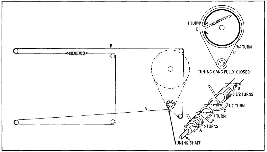
Fig. 2-14. Typical dial-cord stringing arrangement.
Mechanical Defects and Repair
The most common mechanical defect encountered in fm tuners is a worn or otherwise defective dial cord. Dial-cord stringing instructions will be found in the receiver service data, as exemplified in Fig. 2-14.
When the dial cord is not functioning properly, the tuning-scale indication will be incorrect. In permeability-tuned designs (see Fig. 2-15), a spring-loaded gear drive is often employed. In case of binding, erratic operation, or complete failure, look for damaged teeth, a broken tension spring, or foreign matter such as stray pieces of dial cord between the gears. There is also a possibility of stiffness in operation due to dry gear bearings; a drop of light machine oil in each bearing will cure the trouble in this situation. Stiffness in operation is accompanied by a greater torque requirement, with the result that the dial cord may tend to slip on the shaft. On the other hand, cord slippage in normal operation is usually the result of a polished and glazed surface on the cord; if you do not wish to replace the cord, try applying a small amount of belt dressing (no-slip compound).
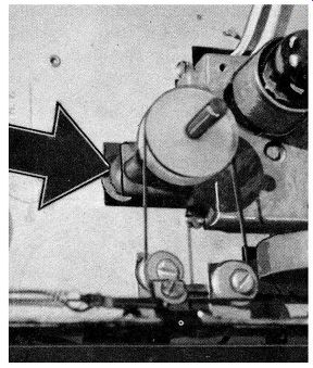
Fig. 2-15.
Arrow points to gear drive in permeability tuner.
Other common mechanical defects include loose shields, partially inserted plugs, insecure PC boards, weak springs, broken resistors and damaged coils (generally due to careless use of tools), stray bits of solder and wire "whiskers," cracked PC boards, and leakage between PC conductors due to contamination with foreign agents such as cleaning preparations or beverages. In fm tuners that have had considerable service, we should also be on guard for broken conductors inside insulated leads. This can be an elusive trouble-maker if the possibility is not kept in mind. Control knobs occasionally become loose on their shafts, and marginal conditions can cause false indexing. Most scale plates are firmly mounted in place; however, if you are unable to make the scale track correctly, check to see whether the clamps may have loosened.
De-emphasis Considerations
To optimize the signal-to-noise ratio in the trans mitted signal, fm stations pre-emphasize the high audio frequencies, as shown in Fig. 2-16A. In turn, a complementary de-emphasis network is provided in the fm tuner, in order to give a flat frequency response with respect to an fm broadcast signal. Fig. 2-16B shows the standard de-emphasis frequency characteristic. It is basically an integrating circuit, or low-pass filter. The standard time constant is 75 µs; the circuit in Fig. 2-17 has a 66-µs time constant, because there is an effective 9 µs time constant in the preceding circuitry. It is evident from Fig. 2-16 that if the de-emphasis capacitor (C86 in Fig. 2-17) should open up, the corresponding trouble symptom will be excessive high-frequency response (tinny sound) at the normal setting of the treble tone control.
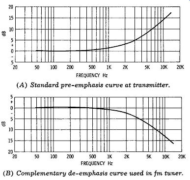
Fig. 2-16. Fm emphasis and de-emphasis characteristics. (A) Standard pre-emphasis
curve at transmitter. (B) Complementary de-emphasis curve used in fm tuner.
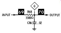
Fig. 2-17. Typical de-emphasis network.
When an fm tuner is designed as a separate package for use either with or without a multiplex adapter, the de-emphasis network is always included in the tuner, following the ratio detector. However, two output connectors are provided, one of which bypasses the de-emphasis network. Thus, when the tuner is used with a multiplex adapter, the de-emphasis network is bypassed, but when the tuner is used without a multiplex adapter, the ratio detector drives the audio amplifier through the deemphasis network. A multiplex adapter contains a built-in de-emphasis network in its output section, so that a flat frequency response is provided. If the multiplex adapter were driven through the DC emphasis network of an fm tuner, the treble level would be very low, and there would be a serious unbalance between the two audio channels.
It is evident that the de-emphasis network in an fm tuner must be bypassed when making a harmonic distortion test, as shown in Fig. 2-12. That is, if we should make the mistake. of passing the output from the fm tuner through the de-emphasis network into the harmonic-distortion meter, an abnormally low reading would result because the higher harmonics would be greatly attenuated. In other words, an fm signal generator or an audio oscillator does not sup ply a pre-emphasized signal. Generators have an essentially flat frequency characteristic; therefore, any test that involves two or more audio frequencies must use a direct connection between the ratio detector output and the indicating instrument. This requirement must be observed in harmonic-distortion and intermodulation-distortion tests, and in an audio-frequency response test such as is shown in Fig. 2-18.
AUDIO OSCILLATOR FM SIGNAL GENERATOR FM TUNER AC VTVM
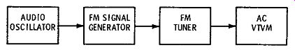
Fig. 2-18. Audio-frequency response test setup for an fm tuner.
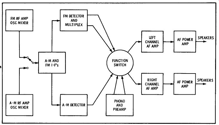
Fig. 2-19. Block diagram of am/fm stereo multiplex receiving system.
The frequency-response test shown in Fig. 2-18 is not customarily made in service shops, because it can be assumed that the audio-frequency response will be satisfactory if the tuned-circuit bandwidths are satisfactory (Figs. 2-10 and 2-11). Although nearly all shops have fm sweep-alignment equipment available, only a very few service benches are equipped with suitable instruments to run the audio-frequency response test shown in Fig. 2-18. An accurate test re quires an RF deviation indicator in the fm signal generator, and only lab-type generators are provided with precision deviation meters.
TROUBLESHOOTING PROCEDURE
Troubleshooting starts with a review of the customer's complaint; useful preliminary data can often be obtained by listening to the customer's account of the difficulty. Tubes are tested as a matter of routine in the case of a tube-type tuner. Operating controls are checked-sometimes the trouble is caused merely by a loose control setscrew. The next step in most cases will be a thorough visual inspection and cleaning. This is an important procedure, which turns up common defects such as broken or disconnected leads, frayed insulation and short-circuits, heat damage such as burned resistors, loose parts, jammed gears, or poor connections. For example, function switches (Fig. 2-19) are often worn by extensive use to a point that their operation becomes erratic.
If repair is impractical, the function switch must be replaced.
Evaluation of the noise level will often provide useful localization clues, as noted previously. For example, if the fm reception is dead or very weak, with a comparatively loud hissing sound across the band, the fm RF amplifier and oscillator (Fig. 2-19) are logical suspects. In a typical case history, this trouble symptom was tracked down to an open-circuited RF transistor. As noted in the previous Section, part of the basic evaluation procedure consists in observing which functions of a combo are affected by the trouble. For example, a common situation involves dead fm and AM functions, although the phono function is normal. With reference to Fig. 2-19, we would suspect the IF section because it is common to both the fm and AM channels. Signal injection with a noise generator or harmonic generator is a useful approach in this situation. In a typical case history, the trouble was tracked down to the second IF transistor; an in circuit transistor tester showed that the transistor was short-circuited.
To repeat an important point, defective transistors can usually be pinpointed by means of DC voltage measurements with a VOM, VTVM, or TVM. Control-action tests are also very useful for confirming suspicious DC voltage readings. Solid-state servicing requires a voltmeter that can indicate 0.1 volt or less with reasonable accuracy. If the instrument also provides a low-range ohms scale, checks of low-resistance tuner components will be facilitated. The base-emitter voltages of germanium transistors normally range from 0.1 to 0.2 volt; silicon transistors normally employ base-emitter voltages from 0.4 to 0.6 volt. A field-effect transistor (FET) differs from a junction transistor in that the control electrode (gate) does not draw current and is not forward biased. In this respect, an FET is similar to a triode tube. There are three basic types, which can be tested with an ohmmeter as shown in Fig. 2-20. Note the basic FET circuit in Fig. 2-21; the source electrode is self-biased at 0.8 volt, in the same manner as a vacuum tube.
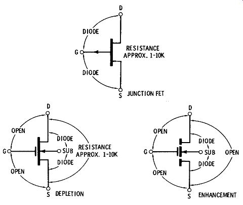
Fig. 2-20. FET resistance checks.
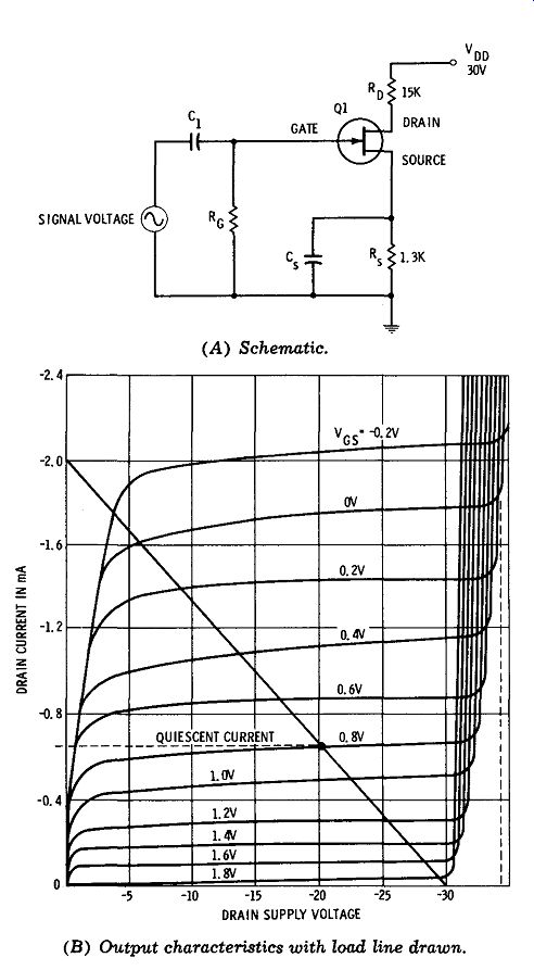
Fig. 2-21. Basic FET voltage amplifier. (A) Schematic. (B) Output characteristics
with load line drawn.
When a frequency-influencing component such as a transistor is replaced, particularly in a high-frequency circuit such as the RF amplifier or oscillator, realignment is often required to restore hi-fi performance and/or proper tracking. Although alignment of the fm IF amplifier is less likely to be affected by transistor replacement, because of its lower operating frequency, it is sometimes necessary to touch up the alignment adjustments in the associated stage.
The effect of replacement transistors on tuned-circuit alignment is a consequence of the tolerance on junction capacitances. Replacement coupling capacitors in the RF and oscillator circuits also have a noticeable effect on alignment and tracking, because of tolerances on capacitance value. A 5-pF capacitor has a reactance of approximately 300 ohms at 100 MHz, and a 10 percent tolerance represents a range of reactance variation from 270 ohms to 330 ohms. In turn, this tolerance corresponds to a frequency variation of approximately 10 percent above or below the normal operating frequency.
ANALYSIS OF COMMON SYMPTOMS
An analysis of the common trouble symptoms listed earlier in this Section is presented in this section.
1. No FM Reception
When there is no fm reception, but the other functions of the combination are normal, the logical conclusion is that the signal is being stopped in the fm tuner. In the case of a tube-type tuner, we check the tubes first.
Possible causes of a dead fm tuner are as follows:
a. Defective or erratic function switch (see Fig. 2-19).
b. Oscillator drop-out. Make a quick check by feeding a cw signal from a generator into the antenna-input terminals at the proper frequency.
c. Shorted capacitor, such as C8 in Fig. 2-7.
d. Open capacitor, such as C34 in Fig. 2-7.
e. Leaky capacitor, such as C41 in Fig. 2-7.
f. Defective transistor; make control-action test, measure dc terminal voltages, or use in-circuit transistor checker.
g. Break in PC wiring; make voltage measurements and continuity checks of suspected conductors.
In case signal-injection or signal-tracing tests show that the signal is stopped by an IC unit (see Fig. 2-7), first check the capacitors associated with the IC terminals, to avoid the possibility of false conclusions.
Most defects in IC packages are accompanied by incorrect terminal voltages, and often by abnormal or subnormal current drain.
2. Weak and/or Noisy Output
When weak or noisy output, or both, are present on the fm function, with normal operation on the AM function, the IF transistors that are common to the fm and AM functions are eliminated from suspicion. In an arrangement such as is shown in Fig. 2-7, the sections that can cause the foregoing symptoms are the fm rf, converter, third £m i-f, or ratio-detector. Stage-gain tests are the most useful approach, al though signal-injection tests will often serve to localize a weak stage. A noisy stage is usually associated with low gain, although there are some marginal defects that produce noise without impairing gain.
A useful quick check consists of shunting a large bypass capacitor from the base of each transistor to ground, starting at the last IF stage and proceeding toward the front end. When the noisy stage is passed, the bypass capacitor will not "kill" the noise.
Possible causes of weak and/or noisy output are:
a. Defective transistor; check oscillator-mixer first.
b. Unstable capacitor (C8 in Fig. 2-7 is a typical example).
c. Open or shorted ratio-detector diode.
d. Unsoldered or cold-soldered connection to PC board.
e. Misaligned rf, i-f, or oscillator tuned circuits (weak output only).
f. Defective IF transformer (tuned circuits can not be aligned properly) .
g. Reflected trouble from fm AGC section. (Check tuner operation using over-ride AGC bias). An fm IF transformer can develop more than one type of defect. For example, an internal fixed capacitor can become open, shorted, or leaky. A winding can be burned out if excessive battery or power supply voltage is accidentally applied. Windings that have been overheated (although not burned out) can develop shorts or leakage between various turns or between layers. Leakage can be caused in humid weather by absorption of moisture. We occasionally find a leakage condition between primary and secondary; this shows up as abnormal transistor terminal voltages, along with the weak-output symptom.
Whenever a tuned transformer is replaced, be sure that the shield is grounded properly, and align the stage carefully.
3. Poor Sound Quality
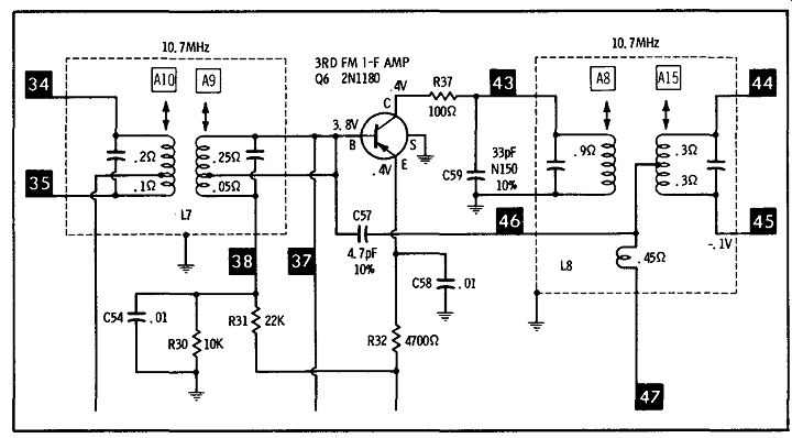
Fig. 2-22. Schematic showing neutralizing capacitor C57.
Poor sound quality will be tracked down to a defective component unless there is an operating fault such as low supply voltage. If poor sound quality is caused by inadequate frequency response, the defect will show up on a frequency-response test (Fig. 2-18), but will not show up on a harmonic-distortion test (Fig. 2-12) . The only exception is a misaligned ratio-detector circuit, particularly a misaligned secondary; this misalignment condition will show up on a harmonic-distortion test. If poor sound quality is caused by nonlinear operation, the defect will show up on a harmonic-distortion test, but not on a frequency-response test. The sure way to localize either type of defect is to use signal injection tests and proceed step-by-step back from the ratio detector, checking frequency response and harmonic distortion.
Possible causes of poor sound quality are:
a. Defective neutralizing capacitor (see C57, Fig. 2-22).
b. Resistor greatly increased in value, such as R104 in Fig. 2-7.
c. Defective or unbalanced components in secondary of ratio-detector circuit.
d. Failing transistor; check terminal voltages.
e. Rf, i-f, or oscillator misalignment.
f. Incorrect replacement transistor.
4. AFC Failure
The basic trouble symptom in case of afc failure is lack of control over local-oscillator frequency drift.
However, there are two ways in which the defect may affect the signal when the afc switch is turned on and off. Thus, the signal may disappear when the afc switch is set to its "on" position. In most cases, the signal will reappear when the receiver is retuned, but the basic lack of frequency-drift control will be observed. Again, the signal may be unchanged when the afc switch is turned on, but with the basic lack of frequency-drift control. Since the afc section is actuated by the ratio detector, substantial defects in ratio-detector operation will also affect afc action.
Possible causes of afc failure are:
a. Defective afc diode, such as X3 in Fig. 2-7.
b. Leaky capacitor, such as C42 or C43 in Fig. 2-7.
c. Worn or erratic afc switch.
d. Incorrect type of replacement afc diode.
e. Resistor greatly increased in value, such as R39 in Fig. 2-7.
When the afc system is operating properly, it will "pull" the oscillator on-frequency when mistuned to either side of a signal. That is, if the afc switch is turned off, and an fm station is tuned in so that it sounds distorted, the distortion normally clears up when the afc switch is turned on. Various fm tuners have different pull-in ranges; therefore, it is helpful to become familiar with current models so that a practical evaluation can be made of the pull-in action.
5. Co-Channel and Adjacent-Channel Interference
Co-channel interference is not always the fault of the tuner; for example, if a receiver is located approximately halfway between two fm stations of equal power and operating on the same channel, co channel interference can be anticipated. In this situation, a directional antenna with a rotor-motor is the only practical solution to the interference problem.
Similarly, adjacent-channel interference is not al ways the fault of the tuner-if an omnidirectional high-gain antenna is used, it may be impossible to prevent powerful adjacent-channel fm stations from "feeding through" when the receiver is tuned to a weak station. In this situation, the practical solution is a directional antenna with a rotor-motor.
Possible causes of co-channel and adjacent-channel interference from tuner defects are:
a. Unbalanced or defective components in ratio detector circuit.
b. Fm AGC trouble, causing RF stage to operate "wide open" continuously.
c. Previous sloppy alignment job, or component replacement in tuned circuit without follow-up alignment check.
d. Defective RF or IF transformer ( cannot be aligned properly) .
e. Incorrect type of replacement RF transformer.
f. Incorrect replacement type of built-in antenna.
g. Defective local-distance switch.
6. Incorrect Dial Calibration
Since fm tuners employ the superheterodyne principle, the same basic causes of incorrect dial calibration apply that were noted previously for AM tuners:
a. Dial-cord stringing incorrect, slack, or loose. See receiver service data.
b. Dial plate incorrectly mounted or shifting in position.
c. Local oscillator incorrectly aligned. Check tracking per receiver service data.
d. Defective capacitor in oscillator section.
e. Shorted turns or other defect in oscillator transformer.
f. Incorrect type of replacement transistor in oscillator circuit.
g. Incorrect type of replacement tuning capacitor.
7. Intermittent Operation
Whenever a puzzling intermittent occurs in an fm tuner, the preliminary tests should be supplemented by monitoring the various circuit sections for the necessary length of time. As in the case of an AM tuner, specialized monitoring instruments can be utilized, or the available meters and scopes can be put to use. It is helpful to energize the fm tuner with a steady signal from an fm generator. The basic monitoring points are at the RF amplifier output, IF amplifier input, IF amplifier output, and ratio-detector output. When the intermittent occurs, the instruments provide localization data without disturbing the circuits. If necessary, the monitoring instruments can be connected next at various points in the defective section, to close in on the defective component.
Possible causes of intermittent operation in an fm tuner are:
a. Local-oscillator drop-out, often due to a marginal defect in the transistor.
b. Mechanical intermittent such as a poor connection; this type of intermittent can often be localized by tapping.
c. Microscopic break in PC wiring; can usually be confirmed by flexing the PC board slightly up and down.
d. Thermally intermittent resistor or transistor; localize by using a heat lamp, followed by a spray coolant.
e. Intermittent capacitor; use monitoring procedures to pinpoint.
f. Marginal defect in tuned coil or transformer; tap with a tuning rod or pencil; press assembly gently from side to side; press terminals while observing output from the tuner.
g. Broken conductor inside of an insulated lead; flex lead while monitoring.
h. Frayed insulation, permitting intermittent short-circuit.
i. Plug not fully inserted into receptacle.