Electromagnetic waves, be they radio or light, are everywhere and keep bumping into each other. Here we look at the problems this causes--and the benefits we can derive from the effect.
SOMEBODY ONCE SAID that he would have great difficulty in describing an elephant but he could recognize one if it walked into the room. Waves are a bit like that--we know a water wave when we see one, but it's difficult to describe what's going on, and it's even more difficult when the wave is invisible (like sound) or if it's a wave that doesn't need any material to move in (like light or radio waves). Well, let's have a go. A wave is an oscillation of something which can spread from one place to another.
A water wave is a lot of oscillating water, and the oscillation of each drop of water in the wave is what makes the next drop oscillate, and so on. A sound wave is an oscillation of air pressure, and an oscillation of pressure in one place causes an oscillation of the pressure further away. An electromagnetic wave, the kind we call light or radio waves, is an oscillation of something less substantial, voltage and magnetism.
Neither voltage nor magnetism is a material, so that electro-magnetic waves, unlike the others we have mentioned, don't need any material to spread from one place to another.
Now the important point about waves is that the oscillation spreads out in all directions from its starting point with a definite speed. Sound waves move at about 330 meters per second in air, electromagnetic waves at about 300 million meters per second in a vacuum, and everything in the path of the wave will be affected in some way. A sound wave, for example, hits materials and makes them vibrate. An electromagnetic wave doesn't make the whole material vibrate, just its electrons, but the action is similar. In each case, the wave that strikes a material causes an oscillation which is a copy of the oscillation that caused the wave in the first place.
Because a wave is an oscillation, though, we can get some interesting effects when two (or more) waves meet. Each wave tries to cause the material, at the place where it strikes, to oscillate but where two waves meet they're trying to make the same bit of material oscillate.
Now two sound waves, for example, can't cause a bit of air to have two different amounts of pressure at the same time, and two radio waves can't cause the same piece of air to have two different voltages at the same time. So what happens? What you might expect, in fact. The amount (or amplitude) of the oscillation is just equal to the sum of the amplitudes of the two waves.
Now this raises an interesting point. Suppose two waves meet, and their peaks line up exactly at the place where they meet (Fig. 1a). From what we know of waves, the amplitude of the oscillation at the place where the waves meet should be the sum of the wave amplitudes, a greater amount of wave. On the other hand, though, if, at the place where the waves meet, the peak of one wave always coincides with the dip (or trough) of the other (Fig. 1b), we would expect the result to be no wave at all Does it happen?
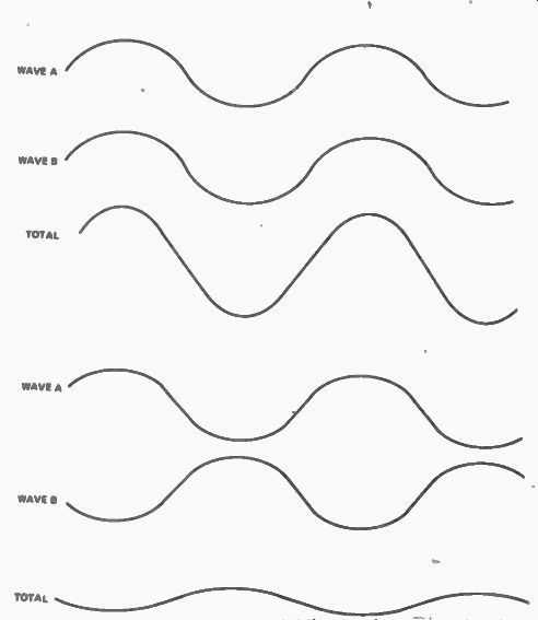
Fig. 1. Wave interference. (a) Adding in phase, constructive interference.
(b) Adding in antiphase, destructive interference.
INTERFERENCE
It does, and the effect is called interference. Waves which add as in Fig. la are said to be in phase, adding constructively; waves which add as in Fig.1 are in antiphase, adding destructively. The interference of sound waves causes the sounds we hear to appear different in different parts of a room. Try this for yourself; if you can hear the whistle from the old telly, shift your head from side to side and notice how the intensity of the whistle changes. This interference effect causes headaches for the designers of concert halls, public address systems and loudspeaker cabinets.
Interference also affects electromagnetic waves, but not always so obviously. Three hundred years ago it was a bit difficult to believe that light was a wave. Had anyone ever seen two beams of light hit a screen and cause darkness where they overlapped? No one had, and it was a long time before the reasons were under stood; in fact many people believed that light could not be a wave.
Reason one is that the wavelength of light, the distance from one peak of the wave to the next, is very small, about a ten-thousandth of a millimeter. The other reason is that light consists of short bursts of waves, not a continuous stream, and that when two light sources send out beams of light the bursts are never in step, so that any interference effects last only for less than the time of a wave burst--and that's not a long time, less than a nanosecond. The technical term for this is that the light sources are incoherent.
THE LUXEMBOURG EFFECT
Radio waves have a much longer wavelength (and so a lower frequency) than light waves; that's the main difference between the two. . They're both electromagnetic waves, they both travel at the same speed, but the interference of radio waves with each other is so obvious that we have to do something about it. In the earliest days of radio the problem hardly existed--there were so few transmitters, the range so short, the equipment was so unreliable anyhow. What was the problem? Well, in the 1920's it became known as the Luxembourg Effect, when that well-known transmitter started broadcasting in English. In the UK, Radio Luxembourg transmissions could be picked up, but they were plagued by alternate fading and 'blasting'. One minute you had to turn the volume control right up to hear anything at all, the next minute you had to turn it right down again to stop it blasting your ears out.
Sounds familiar, doesn't it? The Luxembourg effect is caused by the interference of radio waves--both from the same transmitter, at the same frequency, sometimes in phase, sometimes in antiphase.
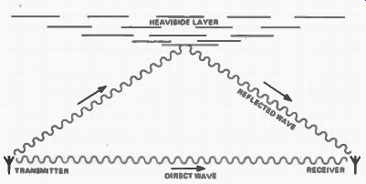
Fig. 2. How reflected waves interfere with the direct wave.
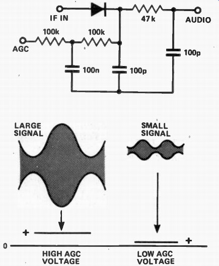
Fig. 3. An AGC circuit and its effect.
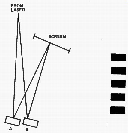
Fig. 4. Laser interferometry (a) set-up. 1, (b) fringe pattern.
Way back in the 1880's, Oliver Heaviside, an electrical engineer who was probably the least understood genius of the last century, had predicted that the action of the Sun's rays on the 'outer edge of the earth's atmosphere, 50 to 150 km up, would create a layer of ions, atoms broken into pieces, which would reflect electromagnetic waves. Since no one at the time was really sure that electromagnetic waves existed (they had been predicted mathematically by Clark Maxwell in 1864), and because Heaviside didn't particularly care if anyone understood him or not, this idea of his didn't exactly make front page news. It rang a very loud bell, however, when the Luxembourg effect was noticed, because it explained why there should be two lots of waves interfering at the receiver.
There is, in fact, more than one layer of ions at the edge of the atmosphere. One layer is called the Heavy side Layer (see Fig. 2.) which is about 50-90 km above the earth, another is named after Appleton, the US pioneer of measurements in the upper atmosphere.
These layers are constantly shifting, affected by the action of the sun and the stirring effect of the movement of the earth beneath them. When a radio transmitter sends out a wave, some of the wave hugs the earth's surface, some reflects from one or more of these layers which act like a huge mirror in the sky. The result at the receiver is a set of waves which have travelled different distances from the same transmitter.
Travelling different distances means that some waves will arrive in phase, some in antiphase. Waves that arrive in phase will reinforce, causing a large amount of signal which can overload the first stages of a radio. Waves arriving in antiphase cause cancellation, so that the signal is weak or missing altogether. Because the reflecting layers are constantly on the move, reception is never steady, so that the Luxembourg effect is, in fact, heard on every medium-to-long distance radio transmission.
You've never heard it? That's because we've devised an ingenious fiddle for counteracting it. Instead of sitting by the receiver alternatively turning the volume up or down, we use a circuit which does this automatically. At the detector of an AM radio, the signal is rectified by a diode. As well as the audio signal, we get a DC voltage at this point, and the size of the DC voltage is equal to the peak voltage of the carrier wave. When the input waves cancel, this DC voltage sinks to zero, when the waves reinforce, the DC voltage rises. (See Fig. 3). We use this voltage to control the amplification, or gain, of the radio signal amplifiers of the radio, so that the gain is turned down when the voltage is high, and turned up when the DC signal is low. The result is that the signal from the detector is almost constant, though you can hear the noise that is picked up increase noticeably when the signal fades (listen for it on a car radio as you drive under some high voltage lines). This system is called AGC (automatic gain control) and it's used on practically all receivers. TV receivers, incidentally, suffer from wave interference effects even if they're near the transmitter, because the waves reflect from aircraft, large vans or other large moving objects to cause just the same problems, though, oddly enough, the Heaviside layer and its relatives cause no bother because the high-frequency waves we use for TV broadcasting pass right through these layers.
MAKING USE OF THE PROBLEM
Strangely enough, this wave interference caper can be turned to some very good uses. One is for very precise speed measurement; it's a system called Doppler Radar. A beam of radio waves is sent out towards a moving object. The waves that return interfere with the waves that are being sent out, causing the usual reinforcement and cancellation. The rate at which this reinforcement and cancellation takes place depends on how fast the target is moving, and can be computed directly, so that the speed of an object can be measured with no contact between the moving object and the measuring instruments. This system is used for radar speed meters and for aircraft altitude meters.
The most precise measurements of distance can be made using the principle of wave interference. Light rays do not normally interfere, because of this incoherence problem we have with light, unless both rays are obtained from the same part of a light source. That very modern light-source, the laser, gives out light beams which stay coherent for a long time. It's possible, therefore, to produce interference between two lase; beams, and it's possible to make use of one laser beam to produce very precise measurements of distance or angle. Figure 4 shows the kind of equipment that is needed.
The light from a laser beam is split, so that one ray is reflected from one object, and another from a second object. If the two rays are allowed to meet on a screen, the interference causes a pattern looking like a set of dark and light bands. Each complete pair of bands represents a difference of one light wavelength in the distance the light has had to travel along the two different paths. Now move one of the objects and the bands will move. If the reflection is at about 90°, a movement of half-a-wavelength of light will cause the band pattern to shift by a complete pair ',dark and light) of bands. For green light, a half-a-wavelength is about 2.5 x 10^-7 m: less than a thousandth of a millimeter.
It's a very sensitive and precise measurement and we can easily detect a shift of much less than a complete pair of bands, so that much smaller changes of position can be measured. This type of measurement, called interferometry, is used for computer control of machine tools. You want to turn 0.01 mm from a piece of steel on a lathe? You set up the laser interferometer, and the computer that controls the lathe, then dial the amount. The tool is racked towards the work, turning starts, and the computer counts the number of bands that go past a photocell used in place of our screen in Fig. 4. When the right number of bands has been counted out, the tool is retracted, the lathe stops, and the machine is ready for the next job.
Need we add that similar methods are used for measuring the thickness of metal and semiconductor, films which make up integrated circuits? It just shows, even interference can have its uses.
(adapted from: Hobby Electronics magazine, Mar. 1979)
Also see: SW Aerials (Antennas)