The traditional long wire receiving aerial for short wave enthusiasts is cheap and easy to set up. There are alternatives, though . . .
SALES OF GOOD QUALITY 'general coverage' receivers with tuning ranges that cover the HF spectrum from 3 MHz to 30 MHz have boomed in recent years, bringing about an upsurge of interest in shortwave listening.
The price of receivers with good 'slow' tuning rates, dial readout to 5 kHz or better, excellent sensitivity and selectivity as well as good stability has decreased to the point where many enthusiasts can afford a 'communications quality' receiver. However there remains a problem with aerials to suit such wide frequency coverage.
WHEN DOES LONG MEAN LONG?
No discussion or description of wide coverage receiving aerials is complete without mention of the ubiquitous 'long wire'. The time-honored long wire is simply what it says--any 'random' length of wire that it is possible to erect in a given space. Theoretically it is 'long when its length is one wavelength or more at the lowest frequency of interest.
No matter, modern receivers are sufficiently sensitive that they only need a whisker of an aerial to pull in plenty of stations at good strength. It's for the weak ones that you need the big aerial.
A typical long wire installation is illustrated in Fig. 1.
The actual height and length depend entirely on your circumstances. A piece of 50mm by 100 mm post is painted and bolted to a fence post or other support, as far from your receiver installation as you can reasonably manage. A pulley, obtainable at almost any hardware store, is fixed to the top and a loop of good quality hemp rope threaded through it, before erection.
An egg or strain insulator is attached to one end of the aerial which is also tied. The other end of the aerial is erected near the receiver installation. An insulator is also attached at this end and the lead-in taken down from it to the receiver installation. The aerial is then supported from this end by tying it off to a chimney, as illustrated.
Having one end of the aerial higher than the other is of little consequence. It'll still work! The lead-in should be taken in such that it clears the house guttering and may be fed through a ventilator opening or over a window sill--whatever is convenient.
Avoid running it for any distance clamped to a wall or parallel to metal guttering, pipes, or wiring. The more direct the better.
Once your long wire is up, you're ready to go! The end of the lead-in can simply be attached directly to the aerial terminal of your receiver.
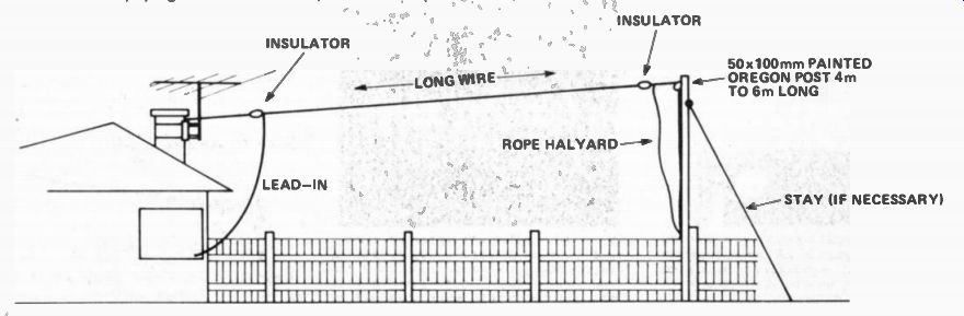
----------Fig. 1. Cheap and relatively simple--the long wire aerial.
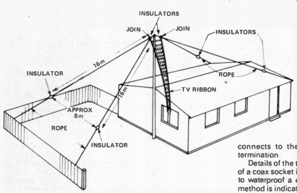
Fig. 2. The 'inverted-vee' aerial (wideband version).
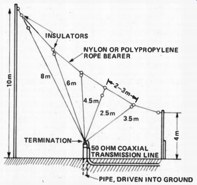
Fig. 3. A broadband version of the HF groundplane aerial.
' VEE HAVE WAYS OF TUNING IN'
A wideband "inverted-vee" style of aerial is illustrated in Fig. 2. This works extremely well across the range from about 5 MHz up to 30 MHz and uses ordinary TV ribbon for a feedline. However, a balun or an aerial tuner is necessary. A balun is simple but an aerial tuner will give better results.
Good signals will be picked up by this aerial right down to 2 MHz but at these low frequencies there's no substitute for size and different aerials, designed to operate in these regions, usually provide better performance.
Beggers can't be choosers though, in many circum stances! Construction is quite simple. Again, a 4m or 6m length of 50 x 100 mm post, painted, is erected against a suitable support--shown here as the side of a house. A fence or garage is just as good.
If you can attach a length of aluminum pipe to a chimney mount or to your house gable--well and good.
Just get the center up as high as you reasonably can.
Each leg of the inverted-vee should be six meters long. However, they can be shorter--whatever you can fit, but the performance at low frequencies suffers.
SAY IT WITH RIBBON
The TV ribbon is connected where the opposite legs of the aerial join at the apex. Support the ribbon with standard screw-in TV ribbon insulator standoffs.
Each leg should be individually tensioned with the rope strainers indicated in Fig. 2. Large screw-eyes, obtainable from most hardware stores, screwed into the supports, as illustrated, serve as excellent anchor points and allow the rope to be tightened using an appropriate slip knot (a round turn and two half half-hitches is excellent). Balun and aerial tuner construction, whichever you choose to suit the inverted-vee aerial, will be described in a future article.
STRAIGHT UP
The familiar groundplane aerial, much used in commercial VHF two-way communications systems as base station aerials becomes somewhat cumbersome at the frequencies that interest hams and shortwave listeners, although they are manageable above 14 MHz.
Loaded verticals, short verticals and other forms of the vertical aerial are popular for a variety of reasons, one good one being they have a low impedance, unbalanced feedpoint which suits most receivers on the market today.
If the actual ground is utilized as the ground plane for a HF groundplane aerial, a series of vertical elements can be connected in parallel at the feedpoint to provide a wideband vertical aerial system--which can give an excellent account of itself.
Such an aerial is illustrated in Fig. 3.
Five elements, of different lengths, are arranged in a fan supported from a rope bearer. They are all brought down to a termination which is supported on the top of a piece of pipe which has been driven into the ground.
The joining of the bottom of all the elements at the terminal provides the feedpoint connection. The centre conductor of the 50 ohm coaxial feedline connects to this point and the outer conductor, or braid, of the coax connects to the earth via the pipe supporting the termination.
Details of the termination are shown in Fig. 4. The use of a coax socket is recommended as it is a simple matter to waterproof a coax connector; however, an alternative method is indicated. Waterproofing of the coax plug and cable will ensure that it has a long useful life. The aerial dimensions indicated in Fig. 3 need not be strictly adhered to--some latitude is possible.
BEAR WITH US
Construction is easy if you follow this procedure: lay out the bearer rope first. Insert the insulator ties at intervals of two or three meters as indicated. Attach the insulators that go at the top of each element to these points on the bearer, opens using short lengths of rope or wire. These will have to be subsequently adjusted, so don't tie the insulators on permanently yet.
Next, lay out all the elements, using the lengths as a guide and allow at least one meter at the termination end of each wire so that they can be individually tightened from the termination and when the aerial is erected.
Hoist the bearer rope into position and' adjust the termination ends of the elements so that they come together with the termination insulator about 300 mm above the ground.
Drive the pipe into the ground below this point. Finish everything off as illustrated in Fig. 4. If using a coax socket for the coax connection, mount it on a small aluminum or galvanized steel plate which is mounted to the pipe via a long bolt passed through the pipe, as illustrated.
If you wish, the coax may be buried. However it is advisable to pass it through some flexible plastic conduit and bury the whole assembly. This will prevent damage to the cable (from enthusiastic or ignorant gardeners, dogs, small brothers etc) as well as reducing moisture seepage.
If you want the ultimate in performance, a series of ground wires can be buried about 200-300 mm below the soil surface radiating out from the pipe for a distance of six to ten meters. They should all be connected together at the center and bonded to the pipe. However, keeping the area surrounding the pipe well-watered should satisfy most requirements.
BICONICAL MONOPOLE
Yes I know it sounds funny--looks funny too (except to the dyed-in-the-wool enthusiast!) but this aerial really performs as is attested by the fact that many professional and military receiving installations throughout the world use them.
The biconical aerial is mentioned in all the classic textbooks--so I won't go into it here. Suffice to say that it will readily cover a 4:1 bandwidth and has a low impedance, unbalanced feed. Low frequency performance is reduced of course but it still works sufficiently well to provide reasonable signals well below the low frequency design limit.
FOUR GUYS AND A POLE
A biconical monopole suitable for home-construction (for the enthusiastic!) is illustrated in Fig. 5. A central pole has two cross-arms located low down around which is passed a length of rope. Twelve wires run from the top termination to the bottom termination, all wires being connected together at the termination points. The four wires which pass over the ends of the cross-arms are arranged to act as guys so that the whole assembly is self-supporting.
The most practical height for the central pole is about six meters, although if you can manage something higher, so much the better. The cross-arms are located about 40% of the pole height above the ground. Each cross-arm is about 40% of the pole height long.
Dimensions are given in Fig. 6 for a biconical monopole that will cover the 7 to 30 MHz range.
Specific construction details are left up to the individual constructor. However, the following points should be noted.
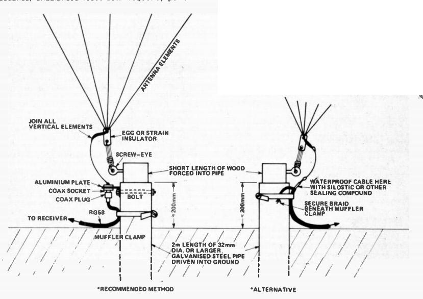
Fig. 4. Two methods of terminating the broadband ground-plane.
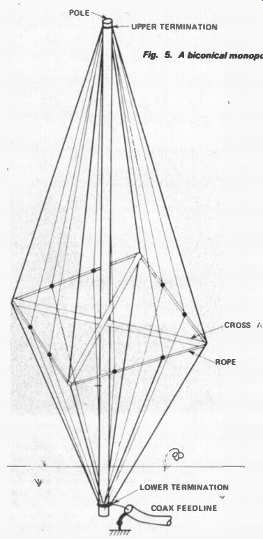
Fig. 5. A biconical monopole aerial.
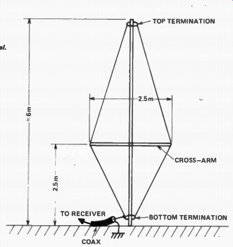
Fig. 6. Dimensions for the biconical monopole.
TYING AND TENSIONING
All the wires should be insulated from the pole and cross-arms, wooden cross-arms are recommended (paint them though). Nylon or polypropylene rope is recommended to go around between the ends of the cross-arms to support the eight wires not used as the guys. Simply tie them with short lengths of wire to the rope to secure them, after tensioning.
All the wires should be joined together at the top and bottom terminations. The bottom termination is the feedpoint. An arrangement similar to that in Fig. 4 should be used to connect the coax feedline. A good ground stake should be used, or better still a ground radial system, as previously described.
INSULATOR HINTS
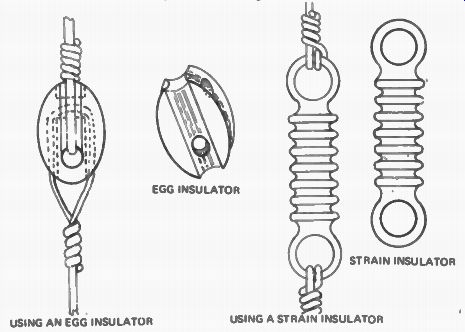
Fig. 7. Two types of aerial insulator and how to attach them.
The aerials described call for the use of insulators at various critical points to insulate the aerial elements from any support or tension rope.
There are two types generally available, the 'egg' insulator and the 'strain' insulator--both illustrated in Fig. 7. Using them is very simple. However, the rope, or aerial wire must be firmly secured where it ties on to the insulator.
GET KNOTTED
Where heavy, standard wire is used, simply wrapping the wire around itself a number of times is usually sufficient. If flexible hookup wire, such as 7/0026 or 10/010 PVC covered, is used then it will have to be knotted to be properly secured. Usually a number of half-hitches following several turns through the insulator eye are sufficient.
Nylon and propylene rope, while cheap and water repellent, deteriorate under the ultra-violet light from the sun and weaken considerably with time. Frequent inspection will indicate when replacement is necessary. Both types creep considerably under strain and the tension will have to be adjusted periodically, but this is only a small chore.
FAIL-SAFE
The insulators illustrated are available in porcelain, nylon and glass. The nylon type egg insulator is usually the least expensive--but they do have one drawback.
After some time in use, the tension of the wire causes the nylon to creep or remold itself and the wire literally pulls itself through the insulator. This may cause the insulator to fail completely. It isn't so much of a disaster however as the aerial wire and support rope are looped through one another and the aerial won't fall down--an advantage of the egg insulator. Periodic inspection and replacement will obviate any problems here.
Good luck and good listening!
(adapted from: Hobby Electronics magazine, Mar. 1979)
Also see: TV Signal Propagation
New Look For Communications Satellites