This section presents several miscellaneous applications of the IC that are supplementary to those in the preceding sections. These additional illustrations serve to round out the picture of IC service.
As in previous instances, the layouts shown in this section may sometimes be combined with those appearing else where in the guide to obtain more complex arrangements for specific purposes. The versatility of the IC is such that layout is often useful for purposes other than the specific one described here.
The setups shown here are primarily illustrative, and therefore are limited to functional block diagram presentation. Where specific values are shown for components, however, resistances are in ohms, and capacitances are in micro farads. A number of ICs, easily available commercially, may be employed in these typical layouts with equal success.
1. INTEGRATOR
Fig. 1 shows the connections for a simple integrator employing an IC operational amplifier. A unit of this type finds application in computing, as well as in instrumentation and control.
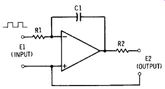
Fig. 1. Integrator.
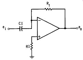
Fig. 2. Differentiator.
This arrangement consists essentially of an amplifier in which feedback is applied between the output and inverting input terminals. The negative-feedback loop consists of capacitor C1. This capacitance, together with input resistance R1, shapes response of the amplifier correctly for integration of the input signal.
The output voltage (E2) is proportional to the integral of the input voltage with respect to time: that is, the output voltage E2 = -(1/R1 C1) inegr. E/dt. Various ranges of operation and response are obtainable by suitable variation of the R1 and C1 values.
For a listing of mathematical applications of the integrator, see any one of the practical handbooks of analog computers.
2. DIFFERENTIATOR
Fig. 2 shows the connections for a simple differentiator employing an IC operational amplifier. A unit of this type, like the integrator, finds application in computing, as well as in instrumentation.
This arrangement consists essentially of an amplifier in which negative feedback is applied between the output and inverting input terminals through resistor Rr. This feedback resistance, together with input capacitance C1, correctly shapes response of the amplifier for differentiation of the input signal.
The output voltage ( e0 ) is proportional to the differential of the input voltage with respect to time: that is, the output voltage eo = -Rf C1 (de/dt). Various ranges of operation and response are obtainable by suitable variation of the Rr and C1 values.
For a listing and explanation of mathematical applications of the differentiator, see any one of the practical handbooks of analog computers.
3. INVERTING ADDER
The IC operational amplifier provides a simple unit for the assembly of an adder. A unit of this type (like the integrator in Section 1 and the differentiator in Section 2) finds application in computing, as well as in instrumentation and electronic control. Fig. 3 shows the connections for a simple adder.
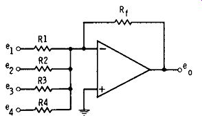
Fig. 3. Inverting adder.
This arrangement consists essentially of an amplifier in which negative feedback is applied between the output and the inverting input terminals through resistor R,. Several input-signal voltages (e1 through e4) may be applied to the amplifier in any desired combination.
All resistances are equal: R1 = R2 = R3 = R4 = Rr. Under these conditions, if all positive input voltages are employed, the output voltage ( e0 ) is the sum of the input voltages: that is, e0 = -( e1 + e2 + e3 + e4). Any desired number of inputs may be added in this manner, provided the output sum never exceeds the maximum voltage swing of the amplifier.
For a listing and explanation of mathematical applications of the adder, see any one of the practical handbooks of analog computers.
4. COMBINATION ADDER AND SUBTRACTER
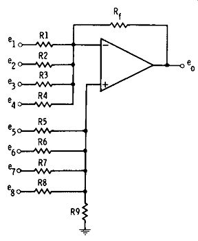
Fig. 4. Combination adder and subtractor.
Fig. 4 shows the connections for a simple combination adder and subtractor employing an IC operational amplifier.
A unit of this type (like the others described in Sections 1, 2, and 3) finds application in computing and also in instrumentation and electronic control.
This arrangement consists essentially of an amplifier in which negative feedback is applied between the output and inverting input terminals through resistor Rr. The input signal voltages to be added ( e1 throughed are applied through resistors R1 through R4 to the inverting input; the input-signal voltages to be subtracted (e5 through es) are applied through resistors R5 through RS to the noninverting input.
All resistances are equal: R1 = R2 = R3 = R4 = R5 = R6 = R7 =RS= Rr.
All input-signal voltages are positive. Under these conditions, the output voltage ( e0 ) remainder results from the application of minuend (e1 through e4) and subtrahend ( e5 through e8 ) to the input terminals. That is: eo = - ( e1 + e2 + ea + e4) - ( e5 + e6 + e1 + es). Any desired number of inputs may be added and subtracted in this manner, in any combination, provided the output eo never exceeds the maximum output-voltage swing of the amplifier.
5. LOGARITHMIC CONVERTER
Fig. 5 shows the connections for a simple logarithmic converter employing an IC operational amplifier. A unit of this type, like the ones described in the four preceding sections, finds application in computing and also in instrumentation and electronic control.
This arrangement, like the others, consists essentially of an amplifier in which negative feedback is applied between the output and inverting input terminals. In this case, however, the feedback loop includes a logarithmic diode, X1. (Some conventional small-signal diodes may be operated in the logarithmic, or quasi-logarithmic, portion of their volt/ ampere response characteristic, if the special diode is not available.)
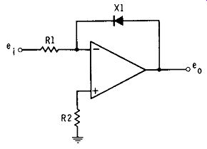
Fig. 5. Logarithmic converter.
In this setup, R1 = R2. Under these circumstances, the output voltage is proportional to the common logarithm of the input voltage. That is, e0 = log10e1.
For a listing and explanation of mathematical applications of the converter, see any one of the practical handbooks of analog computers.
6. VOLTAGE REGULATOR
The integrated circuit has greatly simplified the design and construction of voltage-regulated DC power supplies by providing the DC amplifier needed for control. Still further simplification has been provided by special ICs that include the entire voltage regulator circuit and thus require no outboard components.
Fig. 6 shows the connections for a DC voltage regulator employing a Type D13V IC. This IC is supplied in a T0-98 package and, as shown in Fig. 6, contains the transistors (Q1 and Q2), zener diode (X1), and bias resistor (R1) needed for a shunt-type voltage regulator. This simple arrangement permits close regulation of DC voltages between 10 and 40V at power levels up to 400 mW.
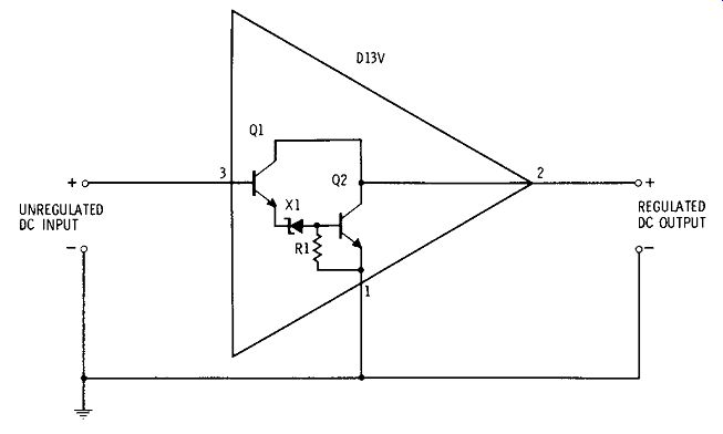
Fig. 6. Voltage regulator.