The integrated circuit simplifies, and sometimes improves, the design of any test instrument in which the amplifying waveshaping, or digital functions of the IC may be employed.
This includes a considerable range of application, and the electronics specialist will have little trouble determining the effective use of ICs in signal generators, meters, converters, counters, and similar test instruments.
This section describes a number of adaptations of the IC to basic test equipment. From these illustrations, other sometimes more complex and sophisticated-uses may be visualized. Aside from these examples, other setups discussed in earlier sections may also be used in, or as, test instruments. See, for example, Sections 2.3, 2.5-2.9, 2.12 2.16, 3.1-3.7, 4.6, 4.8-4.10, 5.6, and 5.7.
Where specific operating constants are given, unless shown otherwise on the schematic or in the text, capacitances are in microfarads, resistances are in ohms, and electrolytic-capacitor working voltage is 25 V dc.
1. IC AS INSTRUMENT AMPLIFIER
Test instruments such as electronic voltmeters, oscilloscopes, and signal tracers occasionally are insensitive for a particular measurement, and a suitable external preamplifier is required. The IC, because of its high gain and wide pass band, often may be used as an instrument amplifier, with the minimum of outboard components. Usually, a single IC will suffice, but two or more units may be cascaded for increased gain.
The IC is selected for appropriate overall gain, frequency response, input impedance, and output impedance. Some times, phase relations also are important. The designer will often find several ICs that are equally well suited to his requirements for an instrument amplifier. When minimum loading of the signal source is imperative, the IC must have FET input; otherwise, a field-effect transistor must be connected ahead of the IC as an input-impedance converter.
The ICs listed as wideband amplifiers or video amplifiers are suitable for this application. (See, for example, Section 2.16, Section 2.) Overall response of the unit may be modified as desired by use of appropriate outboard components.
The user should bear in mind, however, that feedback, external loading, and signal-source impedance sometimes cause marked changes in the characteristics specified by the IC manufacturer.
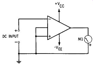
Fig. 1. Basic electronic voltmeter.
2. BASIC ELECTRONIC VOLTMETER
The electronic voltmeter, with its well-known advantages, has occupied an important place in electronic testing ever since the first appearance of the vacuum-tube voltmeter. The transistorized voltmeter is one of the line of such instruments.
The differential-input operational-amplifier IC offers the symmetrical circuit that is valued in the electronic voltmeter.
Fig. 1 shows the basic arrangement. The DC input signal is applied to the inverting input terminal; the noninverting input terminal is grounded. The single output terminal is connected to the DC milliammeter or microammeter, Ml. The degree of balance between the two amplifier sections of the IC usually is so close that if DC supply voltages Vee and Vee are equal there is initially no current through the meter and no need for a zero-set adjustment.
A DC signal (test voltage) applied to the +DC INPUT terminal unbalances the circuit and causes a negative DC output voltage to appear. This, in turn, drives the meter.
The signal voltage required for full-scale deflection depends upon the gain of the IC. One advantage of the electronic voltmeter is its high input impedance, but this is obtained in the simple arrangement in Fig. 1 only if the IC has high input resistance. For immediate results, an IC having FET input should be employed; otherwise, an outboard FET stage must be operated ahead of the IC. To adapt the simple circuit to multirange voltage measurement, the designer need only provide a suitable input range switching circuit in the usual way at the input of the basic circuit (this is done in Figs. 2 and 3). The basic arrangement is for DC voltage measurement. For ac operation, a suitable rectifier may be operated ahead of the basic circuit or ahead of the indicating meter.
3. DC VOLTMETER/MILLIVOLTMETER
Fig. 2 shows the circuit of an IC-type electronic DC voltmeter/millivoltmeter. This instrument offers four ranges: 0-10 mV, 0-100 mV, 0-1 V, and 0-10 V. This arrangement, employing a Type 4009 IC, is seen to be similar to the basic circuit (Fig. 1), except for the addition of the range switching circuit (R1-R2-R3-R4-S1) and the negative-feed back loop (R5-R6). The range selector circuit is a series multiplier, consisting of resistors R1 to R4 in a series string. This arrangement causes the input resistance of the instrument to vary with the voltage range, extending from 100,000 ohms at 10 milli volts to 100 megohms at 10 volts. In applications in which this varying input resistance might be undesirable, the conventional parallel voltage-divider circuit may be used (as in Fig. 3), provided a FET input stage is operated ahead of this IC. The input resistance then will be constant at a single high value, say, 100 megohms.
The resistors in the input circuit (R1-R4) should be ac curate within at least 1 percent. For close calibration, a 1000-ohm wirewound CALIBRATION rheostat may be connected in series with meter Ml.
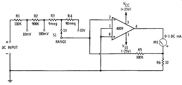
Fig. 2. DC voltmeter /millivoltmeter.
The negative feedback provided by M1, R5, and R6 stabilizes operation of the circuit and increases the input resistance of the IC beyond its normal level.
Fig. 3. AC voltmeter /millivoltmeter.
4. AC VOLTMETER/MILLIVOLTMETER
Fig. 3 shows the circuit of an IC-type ac voltmeter/ millivoltmeter of the amplifier-rectifier type. This instrument offers six ranges: 0-10 mV, 0-100 mV, 0-1 V, 0-10 V, 0-100 V, and 0-1000 V. The input resistance is constant at 10 megohms. All resistors in the input range-switching circuit (R1-R2-R3-R4-R5-R6-S1) must be accurate within at least 1 percent.
For high input resistance, to permit operation of the conventional, parallel input-voltage divider (R1-R6), a FET (Q1) is operated ahead of the Type 4009 IC as a source follower. This FET-IC combination has a frequency response of 50 Hz to 100 kHz.
The ac output signal of the IC is applied to a bridge rectifier circuit (X1-X2-C3-C4), and the resulting dc drives the 0-1 DC milliammeter, M1. In this circuit, X1 and X2 may be any general-purpose germanium diodes, such as Type 1N34A. A portion of the output signal develops a voltage drop across the 10-ohm resistor, RIO, and this in turn is applied (through resistor R9) as negative-feedback voltage to the inverting input terminal. The feedback stabilizes operation of the IC and linearizes the meter response.
For close calibration, a 1000-ohm wirewound rheostat may be connected in series with meter M1, or the 100,000-ohm input resistor R8 ( or a portion of this resistance) may be made variable.
5. SQUARE-WAVE MULTIVIBRATOR
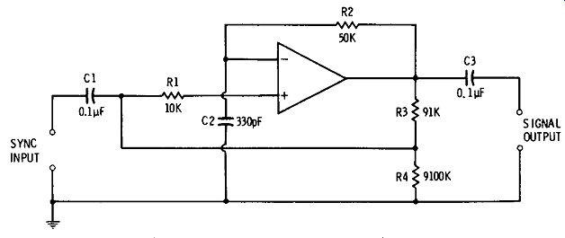
The utility of square waves in electronic testing, and the usefulness of the multivibrator as a frequency divider are well known to the reader. Fig. 4 shows the connections for a simple IC multivibrator that delivers a reasonably good square-wave output signal. Virtually any convenient differential-input operational-amplifier IC may be used. This arrangement may be used as a square-wave generator or as a frequency-dividing multivibrator for use with frequency standards and control equipment.
In this arrangement, negative-feedback voltage is applied to the inverting input terminal through the RC voltage divider, R2C2. Simultaneously, positive feedback derived from the voltage divider R3R4 is applied to the noninverting terminal through resistor R1.
The oscillation frequency is determined by the values of R2 and C2:
f = 1/6.28R2C2 where,
f is the approximate frequency in hertz,
R2 is in ohms,
C2 is in farads.
The values shown in Fig. 4 are those required for 10-kHz operation.
A sync signal, applied at the SYNC INPUT terminals, is injected into the noninverting channel of the IC when the multivibrator is used for frequency division and for closely controlled oscillation.
The square-wave amplitude is a function of the DC operating voltage of the particular IC used.
Fig. 4. Square-wave multivibrator.
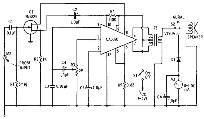
Fig. 5. AF /RF signal tracer.
6. AF / RF SIGNAL TRACER
In many types of electronic servicing, a signal tracer is a handy instrument for localizing trouble. In its conventional form, this instrument gives both visual and aural indications of signal strength and can be used to follow AF and RF signals through a circuit. It is usually untuned.
Fig. 5 shows the circuit of such a signal tracer, employing an outboard FET amplifier for high input impedance and an IC type of complete AF amplifier to drive the loud-speaker and output meter. The IC is a Type CA3020, which contains complete preamplifier, driver, and C1ass-B output stages. Operated from a 6-volt DC source, as shown here, the audio output is in excess of ½ watt, which is ample for this service. The input impedance of the instrument is approximately 5 megohms, the resistance of the gate resistor, R1.
Either an AF probe or RF (demodulator type) probe is plugged into input jack M2 to follow an amplitude-modulated test signal through a circuit under test. Tracer sensitivity is adjustable by means of the 5000-ohm gain-control potentiometer, R3. The output transformer, T1, is a miniature, transistor-type unit for matching 125 ohms center tapped to 3.2 ohms. The single-pole, double-throw selector switch, S2, permits the selection of either aural indications (via the loudspeaker) or visual indications (via the rectifier-type meter, X1-C6-M1).
7. SECONDARY FREQUENCY STANDARD
Any one of the RF oscillators described in Section 3 may be used as a frequency standard, provided it is operated from a steady DC supply and tuned to 100 kHz or 1 MHz. The self excited oscillators may be synchronized with WWV standard frequency broadcasts by tuning their tank circuits for zero beat with the station carrier (this applies to the units described in Sections 3.5 and 3.6). The crystal oscillator ( Section 3.7) may be synchronized by tuning the crystal a small amount with a small variable capacitor (10 to 30 pF maxi mum) connected in parallel with the 100-kHz or 1-MHz crystal.
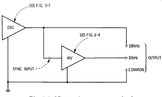
Fig. 6. IC-type frequency standard.
Fig. 6 shows the connections for a frequency standard employing IC-type oscillator and multivibrator. A unit of this type will supply 100-kHz and 10-kHz check points. The oscillator may be the crystal oscillator described in Section 3.7, Section 3, and the multivibrator may be the arrangement described in Section 6.5. The oscillator output terminal is connected to the SYNC INPUT terminal of the multi vibrator, as well as to the 100-kHz output terminal.
8. TEST OSCILLATORS
The oscillator circuits described in Section 3 may be used for signal generators, provided they are operated from steady DC supplies and are equipped with output controls as explained in Section 3.
The Wien-bridge AF oscillator lends itself very well to wideband operation and is the basis of most RC-tuned audio oscillators used in laboratory and service work: R1 and R2 are made the two sections of a 2-gang potentiometer in which R1 = R2 at all settings. Capacitors C1 and C2 are switched in identical pairs to change ranges. An output control potentiometer may be connected between amplifier stages of the IC.
The transformer-tuned audio oscillator is useful especially for single-frequency applications and may be adjusted for good sine-wave output. The RC-tuned audio oscillators have excellent sine-wave output.
The transformer-tuned RF oscillator is easily adapted for multiband operation by arranging L1 and L2 to be plugged in. The crystal oscillator is, of course, basically a spot-frequency device. But this circuit may be adapted to multi-frequency operation by means of a number of selected crystals arranged for switching into and out of the circuit.
The combination oscillator may be used at either audio or radio frequencies, depending upon the characteristics of the plug-in coil-capacitor combinations, L1-C1.
An output-control potentiometer may conveniently be connected between stages of the IC amplifier, or may be added to the output.
9. NULL DETECTORS
The electronic voltmeters described earlier in this section may be used as sensitive, bridge null detectors. The DC instrument (Section 6.3) is satisfactory for use with DC (Wheat stone) bridges and with some millivolt potentiometers. The ac instrument (Section 6.4) is satisfactory for use with ac bridges (impedance bridges, capacitance bridges, inductance bridges, and T-networks). Although these voltmeters do not employ center-zero indicating meters, such as are found especially in many DC null detectors, their operation occasions little difficulty in reading response both above and below null. Each instrument possesses sufficient sensitivity to suit it efficiently to use in standard bridge circuits, with negligible loading of the measurement circuit.
10. DISTORTION METER
The bandstop amplifiers described in Section 2 may be used with some success for the measurement of total harmonic distortion. Either the RC-tuned unit (Fig. 2-7) or the LC-tuned one (Fig. 2-8) may be used. The response of each amplifier may be sharpened by connecting a 50,000-ohm negative-feedback resistor from input to output, i. e., from terminal 1 to terminal 5 in either circuit. The amplifier must be tuned to reject the fundamental frequency of the high purity sinusoidal test signal. An electronic ac voltmeter is connected to the amplifier output.
The test technique is well known to electronics specialists and will be reviewed here only briefly: Since the fundamental frequency is removed by the bandstop amplifier, the out put voltage of the amplifier contains harmonics only. If the test voltage (fundamental plus harmonics) is measured at the point at which it is applied to the equipment under test, and then the output of the bandstop amplifier (which is connected to the output of the equipment under test) is measured, the distortion percentage may be calculated from these two voltages. Thus, Do/a= 100(V0 /V1), where V1 is the applied test voltage, and VO is the output voltage of the band stop amplifier.
The LC-type circuit is suitable for spot-frequency testing only, since the inductor and capacitor required at audio frequencies are too large electrically to be made variable. The RC-type circuit , however, may be made continuously tunable if R1, R2, and R3 are made the sections of a 3-gang potentiometer, and capacitors C3, C4, and C5 are switched in trios to change ranges (see Section 2.8, Section 2). Unless extraordinary care is exercised in the layout and wiring of the bandstop amplifier and ac voltmeter, the fundamental-suppression method of distortion measurement will be limited to frequencies below about 5 kHz. Above this frequency, stray reactances in the circuit cause attenuation of harmonic-frequency components, as well as obscure the null.