| PREV:
| NEXT: |
AMAZON multi-meters discounts AMAZON oscilloscope discounts
AMAZON multi-meters discounts AMAZON oscilloscope discounts
The objectives of this section on Solid-State Devices Used in Industrial Logic Circuits are to help you:
1. Identify the three parts of a control circuit and explain the function of each.
2. Explain the operation of a relay including the function of the coil and contacts.
3. Explain the terms poles and throws in regard to relay contacts.
4. Explain how the contacts and coil of a relay can be used to provide logic and make decisions.
5. Explain the function of normally open (NO) and normally closed (NC) relay contacts.
6. Describe the operation of the circuits provided in this section and explain how the logic controls the circuit operation.
7. Explain why signal conditioning may be necessary for inputs to logic circuits.
8. Explain why amplifiers may be required for the output stage of logic circuits.
9. Explain the operation of AND, OR, NOT, NAND, and NOR gates.
10. Compare the features of solid-state logic de vices and relays.
OVERVIEW OF LOGIC USED IN INDUSTRIAL LOGIC CIRCUITS
Machines in industrial applications require control systems that range from basic to complex in order to operate efficiently and to provide safety. Even though these control circuits may seem vastly different, they are in fact very similar. Each electrical control circuit in an industrial system can he broken into three basic parts: input, decision, and output. When you understand the function each part of the system plays, it's easier to troubleshoot complex control systems.
The first part is the input section. Its function is to provide a link between the control circuit and the world around the machine. For instance, input switches such as limit switches provide information about the position of various parts of the machine. Pressure switches provide information about the line pressure of hydraulic and pneumatic parts of the machine. Push-button switches provide an interface between the machine and human operators who activate the push buttons to start or stop the machine. A touch screen on a modern machine can be used in place of switches as an interface between the operator and the machine. All of these examples are part of the input section of the control system. ill. 1 (below) shows an example of the three parts of a circuit.
The second part of the system makes decisions and is called the logic section. The decision-making part of the circuit is sometimes difficult to define because it may use the same input switch contacts that were described as the input part of the circuit. For instance, if an industrial oven has two doors that both must be closed before the electric heat can be energized, the two limit switches that indicate that the doors are open or closed are part of the input section of the circuit because they tell the condition of each door. Since both door limit switches are wired in series, switch 1 and switch 2 both must be closed to indicate it's permissible to start the oven. Thus the same two switches become part of the decision-making (logic) part of the circuit as well as being the input part of the circuit.
The output part of the circuit causes action to occur. In the case of this example. the output will be a large relay called a magnetic contactor. The contactor is similar to a relay except its contacts are larger in order to handle the currents necessary to operate the electric heating element of the oven. Other examples of outputs are motor starters, which are special relays that incorporate overcurrent protection for the motor, solenoid valves, which are magnetic coils that are specifically designed to move a valve open or closed, and indicator lamps. The contactors, motor starters, and solenoids can also be considered amplifiers because they generally are powered with smaller voltage and current than are used by the device they energize and dc-energize. For instance, the coil of the contactor may be energized by 110 volts ac and use 300 mA to energize, while the electric heating element that it controls may use 480 volts ac and 50 A.
Traditionally, the inputs for the circuit will be found on the left side of the circuit, and the output will be found on the far right side of the circuit. The decision part of the circuit is determined by the way the input switches are connected in series or parallel to enable the output. This means the switches are the inputs for the circuit, and how they are connected is the decision part of the circuit. 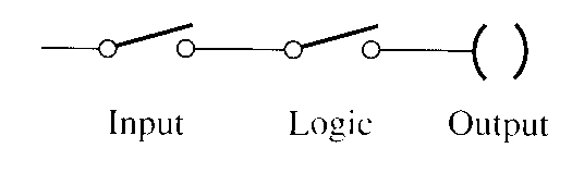
Above: ill. 1: Example of the three parts of a control
circuit: input, logic, and the output. Input, Logic, Output.
| Top of Page | PREV:
| NEXT: |