| PREV: CONNECTING INPUTS TO SOLID-STATE DEVICES | NEXT: SOLID-STATE RELAYS |
The signal that comes from the output of the logic circuit is a low-voltage, low- current signal that's too small to drive a solenoid or motor starter. This means the logic output signal must be amplified to be usable. Several methods are available to amplify the output signal. A power transistor can be used as a stand-alone device, or several transistors can be used in an amplifier circuit. Other solid-state devices called thyristors can also be used. Some of the thyristors that are commonly used are silicon controlled rectifiers (SCRs) and triacs, These devices can switch large dc and ac voltages and currents with small gate voltages.
AMAZON multi-meters discounts AMAZON oscilloscope discountsThe operational amplifier (op amp) is used to drive the solenoid or motor starter. The op amp can be used as the amplifier part of the circuit or it can be incorporated into the logic circuit. A large variety of logic circuits can be designed with op amps. Figs. 1a and 1b show examples of transistor amplifiers used to amplify the output signal of the logic circuit. A detailed discussion of op amps is provided in other areas of this web site.
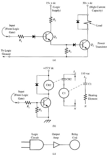
Above: ill. 1: (a) Electronic circuit of two transistors used to amplify the output signal and energize a relay. (b) Electronic circuit of a single transistor and two relays
used to amplify an output signal so that it can energize and de-energize a 240
volts ac heating element. (c) Electronic circuit that shows the output from a
logic gate sent to an amplifier, which energizes a relay.
Two relays can also be used in combination with a transistor to provide amplification and isolation. ill. 1b shows an example of this type of circuit.
From the diagram notice that the output of the logic circuit is connected directly to the base of the transistor. The first relay coil is connected in the emitter- collector circuit of the transistor. A diode is connected in reverse bias across the relay coil (in parallel) to protect the transistor against large transient surges of voltage that occur when the coil is dc-energized and releases its inductive energy back into the circuit. The diode will take this spike of voltage and continually reroute it hack through the wire of the relay coil until it dissipates. The coil of the second relay is connected in the contact circuit of the first relay. The second relay can he significantly larger because the contacts of the first relay only need to apply power to the coil of the second relay.
The amplification part of this circuit takes place in three steps. First, the transistors increase the small-signal voltage from the logic output sufficiently to energize the low-voltage relay coil. In the second step the contacts of the first relay are used to energize the coil of the second relay. The third step of amplification takes place where the 240 volts ac electric heating element is powered by the contacts of the larger relay called a contactor. The small output signal from the logic circuit is able to control the 240 volts ac heating element and turn it on and off as if connected directly to it. ill. 1c shows a diagram of how this circuit would look if the transistors are shown as amplifier symbols. You should also notice that the relay coil is shown as the load to the amplifier. Since the control or logic circuit is shown separately, the heating element that's connected to the relay contacts may not he shown.
| Top of Page | PREV: CONNECTING INPUTS TO SOLID-STATE DEVICES | NEXT: SOLID-STATE RELAYS |