| PREV: Operation of the Solid-State Logic Circuit | NEXT: OUTPUTS FOR LOGIC CIRCUITS |
AMAZON multi-meters discounts AMAZON oscilloscope discounts
|
In the logic circuits that have been discussed so far in this section, the inputs to the logic chips have been described in their most simplistic form. When a simple switch is connected to a logic circuit as an input, several complex problems occur. First, the switch contacts don't close precisely when the switch is activated. Instead the contacts actually bounce against each other several times before the switch settles into the closed position. The technical term for this is contact bounce. If the contacts bounce two or three times, the logic circuit sees this action as though the switch was actuated rapidly open and closed. If the logic circuit is used to count, each bounce of the contacts will be considered one operation of the switch contact closure. That is, the logic circuit would think the switch had actually opened and closed three or four times when the contacts bounce. This should also give you some idea of how fast the logic circuit operates, since the contact bounce occurs in less than several milliseconds. AMAZON multi-meters discounts AMAZON oscilloscope discounts |
One method that's used to solve this problem is to provide a capacitive filter between the switch and the logic gate. The filter actually consists of a resistor and capacitor. The resistor is sized to cause the capacitor to take a few milliseconds to fully charge before its voltage is large enough to trigger the input of the logic circuit. The resistor and capacitor act like a traditional time constant circuit. When the contacts first bounce close, the resistor limits the voltage to the capacitor, which makes it charge over a few milliseconds. The time constant is designed to be slightly larger than the time for the contact bounce to occur. Other more elaborate methods of combating the effects of contact bounce may include types of latches that catch the first bounce of the contact closure and ignore all subsequent bounces.
A more serious problem exists for inputs to logic circuits. This is the problem of voltage and current incompatibility. For instance, the logic circuit is designed to operate at 3-5 volts dc. A 110 volts ac switch from a photoelectric switch is used as the logic input, which can't be connected directly to the logic circuit. The primary voltage of control devices used in industrial machinery is 110 volts ac.
The 110 volts ac switch is used because it's immune to signal noise from motors and other high-voltage devices and because it can be transmitted over longer distances. These types of problems can be solved by a signal converter. ill. 1 shows several examples of signal converters. In the first circuit ( ill. 1a), notice that an isolation transformer is used to drop the 110 volts ac to the correct logic voltage level and diodes are used to convert the ac voltage to dc. The second circuit ( ill. 1b) provides both the voltage conversion and isolation by using a rectifier and optocoupler. The optocoupler is a device that combines a light-emitting diode (LED) with a phototransistor. These devices are discussed in detail in another section of this web site.
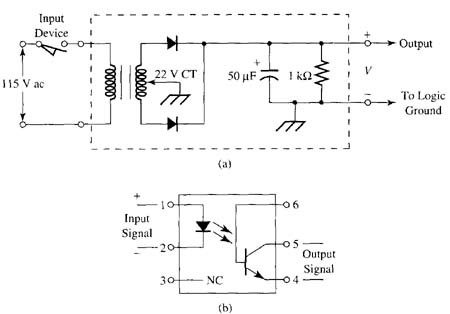
Above: ill. 1: (a) Input circuit for a logic
gate. This circuit provides signal conversion and isolation for 110 volts
ac signal that's used as an input to a logic circuit. (b) Circuit of a
solid- state optocoupler, which uses a light-emitting diode (LED) and photo
transistor to create an isolation circuit for dc signals.
The resistors in the circuit help to drop the 110 volts ac to the acceptable level and the rectifier changes the ac to dc for the LED. The LED emits a light directly to the phototransistor, since the two devices are encapsulated inside an IC. When the phototransistor sees the light, it will go into conduction and reproduce the action of the input switch. The optocoupler provides the additional feature of isolation in that the LED won't transmit the large transient voltage spikes that may occur on the input to the transistor. The intensity of the LED output won't seriously affect the phototransistor, since it's already in saturation. Both of these circuits will still require a bounce elimination circuit, since the switch contact bounce would be retransmitted by both of these types of circuits.
| Top of Page | PREV: Operation of the Solid-State Logic Circuit | NEXT: OUTPUTS FOR LOGIC CIRCUITS |