| PREV: Strengths and Weaknesses of Relays | NEXT: Operation of the Relay Logic for Parts Bin Level Control |
AMAZON multi-meters discounts AMAZON oscilloscope discounts
|
When robots are used in automated work cells, every aspect of the system must be automated. In some applications, robots must take small parts such as screws or bolts from a parts feeder and insert them into the work pieces as they move by an assembly line. Each parts feeder has to have a bin that holds a 1- to 2-hour supply of the small parts. The bin acts as a storage buffer for the small parts, but it's important that the level in the bins is automatically controlled to ensure that sufficient parts are available and that the bin does not overfill or become empty. AMAZON multi-meters discounts AMAZON oscilloscope discounts |
Below, ill. 1 shows the solid-state logic diagram and ill. 2 shows the
relay logic diagram for this system. The system has two bins to feed
parts to two robots. Proximity switches are mounted at the top and the
bottom of each bin to indicate that the parts bin is full or empty. A
gravity-feed system is used to feed screws through a tube so that they
can be loaded directly into each bin. A separate solenoid is used to control
the amount of parts that drop into each bin. If either bin goes empty and does not begin to fill after 2 minutes, an alarm horn (annunciator)
is sounded to warn technicians that the robots are about to run out of parts.
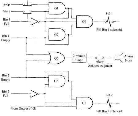
Above: ill. 1: Solid-state positive true logic for the bin-level control system..
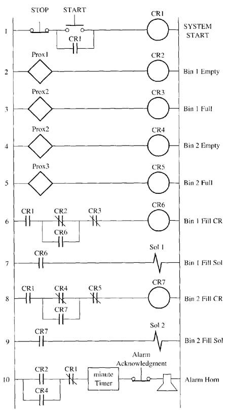
Above: ill. 2: Relay ladder logic for the bin level
control system.
The start and stop switches are connected to the first logic AND gate G1. Since the stop button is normally closed, the gate will provide an output as soon as the start push button is depressed. Since the start push button is a momentary-type switch, the output of AND gate G1 will be used to seal it in. The output of gate G1 is also sent as an input to gate G4. Notice that gate G5 also uses the output of G1 as one of its inputs. This means the first gate (G1) is used to start and stop the entire circuit.
The fill-bin solenoid (Sol 1) will become energized any time the level in the bin drops below the bin-empty sensor. When the level drops below the bin-empty sensor, a 1 is sent to G2. Since the level is also below the bin-full sensor, G2 will receive its second input from the inverter that's connected to the bin-full sensor. The bin-full proximity switch uses an inverter to make sure the signal that's sent to gate G2 is a 1 when the bin is not full. When gate 02 receives both inputs, it will produce an output to gate G4, which is currently receiving an input signal from G1. Notice that the output of G2 is also brought back as an input to gate G2 to seal it in once it's turned on. This is necessary since the bin-empty signal will turn to a 0 as soon as parts are dropped into the bin. Since G2 is sealed in with its output, it will remain energized until the bin is completely full. When the bin becomes completely full, the bin-full sensor sends a I to its inverter, which sends a 0 to 02 and turns it off. When G2 turns off, its output no longer provides a seal- in signal, which keeps the fill solenoid off until the bin becomes empty again. The seal-in signal around G2 ensures that the fill solenoid will remain on any time it's energized until the bin is completely full, and it will remain off any time it's de energized until the bin is empty again. Gates G2 and 04 provide the logic for the first bin, and gates G3 and G5 operate the second bin.
| Top of Page | PREV: Strengths and Weaknesses of Relays | NEXT: Operation of the Relay Logic for Parts Bin Level Control |