| PREV: SOLID-STATE AND RELAY LOGIC CIRCUITS TO CONTROI PART BINS FOR ROBOTIC AUTOMATED WORK CELLS | NEXT: QUIZ |
The parts bin level control system is controlled by a control relay CR1, which is started with a manual push button (start/stop station). Notice that the start button is sealed in by a parallel set of CR1 contacts. The seal-in feature allows the control relay coil to be initially energized by depressing the NO start push button once and releasing it. The stop push button acts as a regular stop button and emergency stop, since it will drop out the CR1 coil any time it's depressed.
AMAZON multi-meters discounts AMAZON oscilloscope discountsThe bin-level empty and bin-level full are determined by proximity switches
that are activated when parts are in front of them. (A detailed description
of the operation of proximity switches is provided in other areas of this
web site.) That is, the low-level proximity will act like a closed switch
as long as parts are near it. If the bin goes empty, this switch will act
like an open switch. The bin-full proximity switch will act as an open switch
as long as the parts level is not full. When the bin fills up to the top,
the parts will be in front of the proximity switch, and it will act like
a closed switch. Each proximity switch is treated as an input to the logic
circuit and is connected to a control relay. The contacts of these control
relays are used to provide the logic for the system.
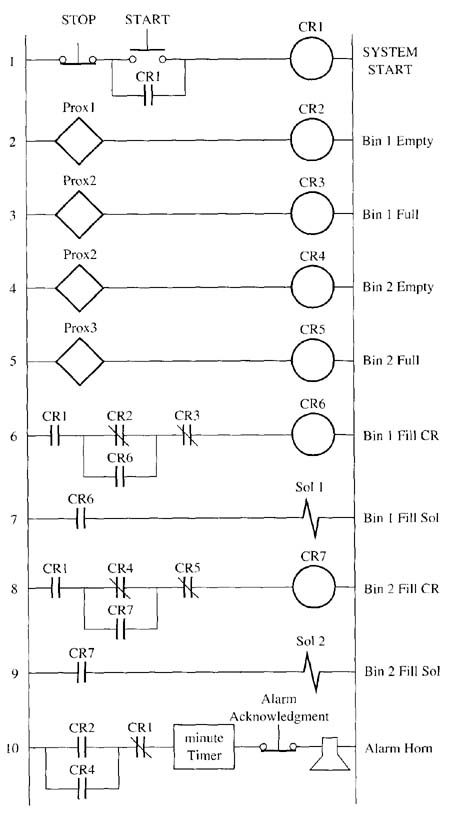
Above: ill. 1: Solid-state positive true logic for the bin-level control system..
The logic for the first bin is controlled by the coil of control relay CR6. Notice that the master start button must be depressed to pull in CR1, since the contacts of CR1 are the first contacts of this circuit. The CR1 contacts are ANDed with NC CR2 contacts (bin empty) and the NC CR3 contacts (bin full). When this line of logic becomes true, the CR6 coil becomes energized and its contacts energize the solenoid valve that opens to allow more parts to drop into the bin.
The important part of this circuit logic is that once the level in the bin is detected as empty, the CR2 contacts will close and pass power through NC contacts CR3 to the CR6 solenoid. After parts begin to fall into the bin, they will fall in front of the low-level proximity switch and turn it off right away. This would normally dc-energize the solenoid immediately, which would cause the system to short cycle. When the system is short cycling, it will only allow a few parts to drop into the bin and shut off prematurely. To prevent short cycling from happening, a set of NO CR6 contacts is placed in parallel (OR) with the CR2 bin-empty contacts. When the low bin level is reached and CR2 contacts close for the first time, the CR6 relay coil becomes energized and pulls in its NO contacts that will provide an alternate path around the CR2 bin-empty contacts. When parts start to fill the bin, and the proximity switch indicates the level is no longer too low, the CR2 contacts will open, but the CR6 coil will remain energized until the NC CR3 contacts open to indicate the bin is full. The CR6 contacts that seal in the CR2 contacts provide a type of dead band. That is, once the low level is reached and parts start dropping into the bin, they will continue to fill until the bin-full level is reached. The solenoid won't be energized again until the bin level reaches the empty point. The amount of dead band is determined by the height of the bin-full and bin- empty sensors.
The circuit for the second robot’s parts bin operates exactly the same as the circuit that was just described. The only difference is that bin 2 uses a bin-empty sensor that activates CR4 and a bin-full sensor that activates CR5. The logic circuit for the second bin uses CR7 to activate the solenoid to allow parts to drop into the bin.
The last part of this automated bin level control is the alarm circuit. The alarm is needed to indicate that one or both of the bins are empty and they have not begun to fill after a 2-minute period. The robot will use up all the parts in the bottom of the bin within 10 minutes of the bin-empty switch activating. The alarm will sound 2 minutes after the bin-empty switch is activated and this will give a technician several minutes to find the problem and fix it.
The logic for the alarm is shown in the last line of this diagram. The NO CR1 contacts ensure that the alarm system is only operational if the system start has been activated and the system is running. Notice that the NC CR2 bin-empty contacts for bin I are connected to a 2-minute timer. If the bin goes empty, no parts will be in front of the proximity switch, so it won't energize the coil of CR2 and the CR2 contacts will close and pass power to the timer. If the contacts remain closed for 2 minutes, the timer will time out and energize the alarm horn (annunciator). A duplicate circuit is provided for the second bin, and contacts CR4 are connected in parallel as an OR logic condition with the CR2 contacts. That is, the horn will sound if either bin goes empty for more than 2 minutes.
| Top of Page | PREV: SOLID-STATE AND RELAY LOGIC CIRCUITS TO CONTROI PART BINS FOR ROBOTIC AUTOMATED WORK CELLS | NEXT: QUIZ |