| PREV: Early Examples of Logic Gates | NEXT: Programmable Array Logic (PAL) |
AMAZON multi-meters discounts AMAZON oscilloscope discounts
|
Programmable logic arrays (PLAs) are part of a new family of logic devices called programmable logic devices (PLDs). The PLAs are similar to a programmable read-only memory (PROM). The PLA is made up of a programmable AND plane, which is connected directly to a programmable OR plane. ill. 1 shows an example of the PLA. Notice that the AND plane has three inputs, I(1), I(2) and I(3) which are part of a matrix. Each input also has a parallel input called its complement. Multiple columns in the matrix are used to connect the AND plane to the OR plane. A fuse and diode are provided at the point in the matrix where the rows and columns intersect. The logic program is entered into the PLA by blowing out the necessary fuse links. When the fuse link is left in place, the logic path is useful, and each time the fuse link is blown out the path is interrupted. Together the intact and blown fuse links provide the logic program. Since this technology is similar to the technology used to program a PROM, the PLA can be programmed by a PROM programmer. AMAZON multi-meters discounts AMAZON oscilloscope discounts |
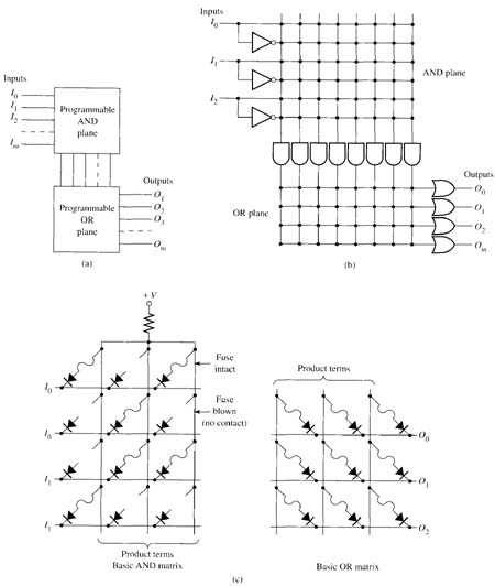
Above: ill. 1: (a) Block diagram of programmable logic array (PLA). (b) Diagram that shows the AND plane and OR plane interconnection. (c) Internal diagram of basic AND matrix and basic OR matrix with fuses and diodes intact and open.
The outputs of the AND plane are called the product terms, which are connected directly to the OR plane where they act as inputs. The diode and fuse connections are again used to connect each row and column. The fuse is blown at specific intersections between rows and columns to program the logic function of the OR plane. The OR plane has a number of outputs that are numbered O1 O2, and O3, and so on. The exact number of inputs in the AND plane and outputs in the OR plane may be selected when the device is purchased.
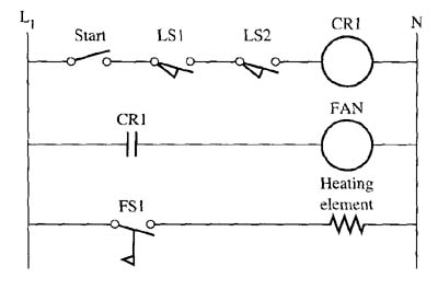
ill. 1 shows the connections between each of the logic segments in a PLA. If a program for a system such as the electric heating oven shown in this figure were entered into a PLA, the specific fuses would be blown to provide the logic. The inputs from the door limit switches would be connected to I2 and I2. The start switch would be connected to input I3, and the flow switch would be connected to I4. The output that indicates it's safe to start the fan would be output O1 and the output that indicates it's safe to start the electric heating element would be O2. Notice that all that would remain to have the PLA provide the logic for this circuit would be to open the necessary segments. When the program is printed, each segment that has active logic is shown as a dot on the intersection. This allows the technician to follow the dots when the circuit must be troubleshooted to determine which outputs would be energized.
PLAs are presently used to replace typical quad logic gates or other multiple logic gates that are mounted on a single 14-pin IC. The PLA is slightly larger than the 14-pin IC, yet it's able to provide hundreds of logic functions while using less power. The PLA can also execute the logic at a much faster speed than traditional ICs. PLAs are also available in a variety of logic functions beyond the traditional AND, OR, and NOT logic, such as exclusive OR (XOR).
| Top of Page | PREV: Early Examples of Logic Gates | NEXT: Programmable Array Logic (PAL) |