| PREV: Transistor Equivalent to AND and OR Circuits | NEXT: Early Examples of Logic Gates |
AMAZON multi-meters discounts AMAZON oscilloscope discounts
|
There are several variations of the transistor AND circuit and the transistor OR circuit. Once you have understood the operation of all the components within each circuit, the circuit can be replaced with a logic symbol. The logic symbol is easier to understand than trying to follow all of the voltages and grounds in a traditional transistor circuit. All you will care about in the logic symbol is the type of symbol that's represented and the conditions of each input. After you have determined the condition of each input, you can use a truth table to determine whether the output will be HI or LO. AMAZON multi-meters discounts AMAZON oscilloscope discounts |
The basic logic conditions can be expressed with five logic symbols. These
are AND, OR, NOT, NAND, and NOR. When the logic symbols are used in a
circuit, they are often called gates. ill. 1 (below) shows an example
of the five basic logic gates and a truth table for each. From this figure
notice that the truth table shows the number of inputs each gate has and the output. A 1 or 0 is showed to indicate all of the possible conditions
for the input. The 1 indicates the input is HI, and the 0 indicates the
input is LO. The condition of the output for each set of inputs is also
shown as a 1 or 0 to indicate if it's HI or LO.
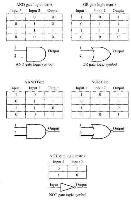
Above: ill. 1: AND, OR, NOT, NAND, and NOR gates with truth tables.
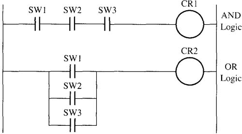
The operation of the AND and OR gates is identical to their counterpart in relay logic shown here. The NOT gate is similar to a set of normally closed contacts in relay logic. When no power signal is applied to the coil of the relay, power will flow through its set of NC contacts, and when a signal is sent to the coil, no signal can get through the NC contacts because the coil has pulled them open.
The NOT gate is also called an inverter because the output is always the inverse of its input. You should also notice in this figure that the NOT gate can be combined with the AND gate to make a NAND gate (NOT + AND), and the NOT gate can be combined with the OR gate to make a NOR gate (NOT + OR). The small circle at the output is used to indicate the inverter or NOT condition has been added to the gate.
| Top of Page | PREV: Transistor Equivalent to AND and OR Circuits | NEXT: Early Examples of Logic Gates |