| PREV: SOLID-STATE LOGIC EQUIVALENT TO THE MERCURY COUGAR TAIL-LIGHT ASSEMBLY CIRCUIT | NEXT: CONNECTING INPUTS TO SOLID-STATE DEVICES |
AMAZON multi-meters discounts AMAZON oscilloscope discounts
|
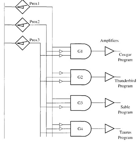
Previously in this section, a system that used relay logic to send a request to robots to execute programs to place studs in taillight assemblies was discussed. This figure (see prev. page) shows the equivalent solid-state control circuit that utilizes AND gates and inverters to provide the same function. The hardware for the solid-state taillight detection system uses a set of three fingers that are mounted on each carrier. When they are lowered, the fingers will trigger a proximity switch just like the relay logic circuit. As you remember from the relay logic system, four different types of taillights can be loaded onto the carrier (Cougar, Thunderbird, Sable, or Taurus). The robot must know which type of taillight is in the carrier because it uses a different program for each taillight to ensure that the correct number of studs are mounted and that they are placed in the correct location. When a taillight is placed onto the carrier, the technician lowers the corresponding fingers to indicate which type it's . AMAZON multi-meters discounts AMAZON oscilloscope discounts |
In the diagram from the previous page, the first proximity switch is connected to the first input of each of the four logic gates. The second proximity switch is connected to the second input of each logic gate, and the third proximity switch is connected to the third input of each gate. Inverters are used to provide the correct logic input. ill. 1 (below) shows a truth table for this operation.
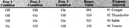
Above: ill. 1: Truth table and binary
equivalent values for the switches in the previously-shown
circuit.
When a Cougar taillight is loaded on the carrier, the first finger is lowered and the second and third fingers remain in the up position. When the carrier passes over the proximity switches, the first proximity is triggered and it sends a HI signal to all four logic gates. The second and third proximity switches are not triggered so they both send a LO signal to all four gates. From the truth table in ill. 1 notice that when this combination of signals reaches each gate, only the Gi gate for the Cougar signal receives the correct combination to provide an output signal. The HI signal that's sent to the first input of gate 2 and gate 4 passes through an inverter, which will cause the signal to go LO so the gate output will be LO, and the LO signal sent to the second input of the third gate (Sable) will cause its output to be LO. When the Cougar logic gate becomes true, it will provide an output to its amplifier and the proper voltage signal is sent to the robot to indicate it should run the Cougar stud insertion program.
When a Thunderbird taillight is placed on the carrier, the second finger is lowered and the first and third fingers remain up. When the carrier passes over the proximity switches, the second switch is activated. Notice in the truth table that this combination of switch 1 (LO), switch 3 (LO), and switch 2 (HI) will only activate the G2 logic gate for the Thunderbird program signal. The first and fourth gates will have a LO logic output because they use an inverter in the line for their second inputs, which negates the HI signal from switch 2. Since the first input is LO for this carrier, the output for the Sable logic gate will also be LO.
When a Sable taillight is placed in a carrier, the first and second fingers are lowered and the third finger remains in the up position. When this combination of fingers passes over the proximity switches, the output of the third logic gate goes HI and the robot is signaled to start the insertion program for the Sable. The Taurus taillight uses the third finger down and the first and second fingers up to trip the proximity switches in the correct sequence.
The sequence of the inputs utilizes a binary code from the proximity switches to provide four possible conditions (outputs) from three input switches. Since the three input signals are interpreted as binary code, up to eight separate signals (0-7) could be generated.
| Top of Page | PREV: SOLID-STATE LOGIC EQUIVALENT TO THE MERCURY COUGAR TAIL-LIGHT ASSEMBLY CIRCUIT | NEXT: CONNECTING INPUTS TO SOLID-STATE DEVICES |