XYZ control uses coordinates instead of points to identify each position the robot moves to during the time it runs its programs. The XYZ control is very similar to the point-to-point control except the entire work envelope is identified by its mathematical coordinates. ill. 1 shows an example of a robot envelope defined as XYZ coordinates. The diagram in this figure is a top view of the robot work envelope. In this example the X-axis is the horizontal axis, and the Y-axis is the vertical axis. But it's important to remember that since this is a top view, the Y-axis is actually the front-to-back axis and it's sometimes called the depth axis. The axis that shows height is called the Z-axis. Since this robot has a pneumatic cylinder for the up/down motion, the Z-axis is not listed in the diagram. When one is programming one would simply indicate that Z location is either up or down.
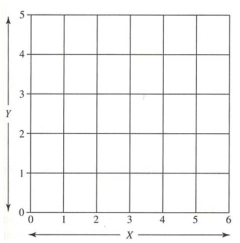
Above: ill.1 Example of a robot work envelope identified in XYZ coordinates.
The size of each square in the grid is 1 centimeter (cm) and the middle of the grid is considered point X0, Y0. When the robot is programmed, points X, Y, and Z are indicated for each step. Since the entire work envelope is identified within the X, Y, and Z coordinates, the robot program can be written at a different location than right at the robot. The program could also be developed from a computer-aided design (CAD), computer-aided manufacturing (CAM) system. In other words, a computer can help identify the points the robot must move to in a program, and by determining the X, Y, and Z coordinates of each position, they can be entered in the program in the sequence they occur.
When the robot executes the program, it will move in a straight line or arc as specified as the robot moves from point to point. This type of program is useful in ensuring the robot moves along a straight-line path to move from one point to another. This type of program is also useful when the robot must move in arc or circles because the radius or circumference can be specified mathematically. One advantage of this type of control is that the technician can determine where the robot should be at any time during the program by identifying the point in XYZ coordinates. This type of program is also used in computer numerical control (CNC) equipment.
ill. 2 shows an example of this type of program where one can notice that each step is numbered so the technician can identify them. Each step consists of a location identified in XYZ coordinates, and any codes to turn on (S80, 1) or turn off any output signals (S81, 1). The speed the robot should move between each step is identified as an F code, where F indicates a feed rate.
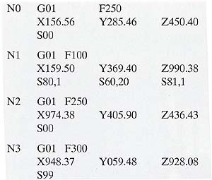
Above: ill. 2: Example of an XYZ program for a robot.
| Top of Page | PREV: | NEXT: |